Kele Blog

Hazardous Atmospheres: Explosion Proof

Reprint from Spring 1999 Insights

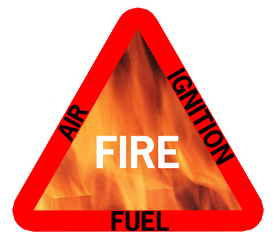
In the last edition of 20/20 Insights we discussed the elements that must be present in order to produce an explosion. The three legs of the “fire triangle” (fuel, oxygen, and an ignition source) are required to support combustion. In addition, the volume ratio of fuel to air must be within the fuel’s explosive limits, and the ignition source must release sufficient energy to ignite the mixture. Removing any of these three elements will eliminate the explosion hazard.

Perhaps the most common and familiar way to eliminate ignition sources from a hazardous location is through the use of explosion proof construction. An enclosure that is rated explosion proof (NEMA 7, 8, 9, or 10) for a particular hazard group (explained below) is strong enough to withstand the pressure of a worst-case explosion inside itself. Additionally, it is designed to vent the resulting hot gases in such a way that they are cooled below the ignition temperature of a worst-case explosive mixture outside the box.

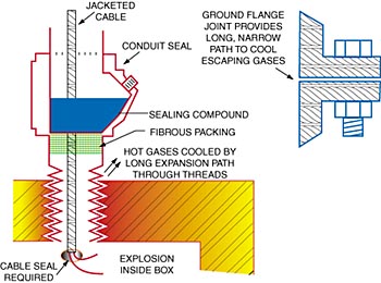
To contain the pressures of an explosion, these enclosures are made from heavy cast steel or cast aluminum. To cool escaping gases, flanged enclosures have extra-wide flanges that are ground to a smooth finish and tight tolerance – thus yielding a very thin, very long path to the outside as shown in the illustration. Enclosures with threaded covers (and threaded connections to either type of enclosure) produce the same effect by virtue of the long, narrow path through the threads. As the hot gases from an internal explosion pass through these long, narrow channels, they give up heat to the metal and their pressure is reduced. These two effects team up to lower the temperature of the gases to a safe level before they can come in contact with the atmosphere surrounding the enclosure.

With flanged enclosures, it is very important to torque the cover bolts evenly and as close as possible to the recommended value. Also, the flange surfaces must not be scratched or marred in any way. Improper torque or damaged surfaces can allow hot gases to escape and ignite an explosive mixture outside the enclosure. Threaded connections or covers must engage at least five full threads to maintain the integrity of the system.

One additional step is needed to control the spread of hot gases – conduits entering the enclosure must be sealed within the code-required distance (usually 18”) of the box to prevent the buildup of pressure within the raceway system or the leakage of combustion products into the room. If a jacketed cable passes through a conduit seal, the jacket should be removed within the seal so that the sealing compound can completely surround each insulated conductor. An alternative is to seal the cable at the end of the jacket as shown in the illustration.

So where can these types of enclosures be used? As usual in our industry, there are no easy answers! Each explosion proof enclosure will be listed or labeled for use in a particular environment as defined in the National Electrical Code (NEC) or IEC Standards. In turn, the hazardous area itself must be classified according to the same standards. The enclosure must have a listing that meets or exceeds the classification of the area in which it is to be used. In the NEC, considerations are Class, Division, and Group as shown in the table below. IEC standards use different code letters from the NEC but generally follow the same logic.

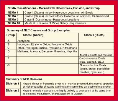
For gases (the majority of our industry’s hazards), explosion proof enclosures are readily available for Class I, Division 1, Groups C and D. Enclosures rated for Group B (hydrogen) can also be found, but generally only in small sizes since it is so easily ignitable and has high explosive energy. Almost nothing is offered for Group A (acetylene) environments because of its easy ignition and tremendous explosive energy.

Using explosion proof enclosures removes the ignition leg from the “fire triangle” in a potentially hazardous location. Although it is costly and requires care to maintain the system’s integrity, it is an effective method for working with electricity in combustible atmospheres. In a future 20/20 Insights we will discuss intrinsically safe systems, another way to remove potential sources of ignition from hazardous locations.

Hazardous Atmospheres: Introduction

Reprinted from Winter 1998/1999 Insights

Automation dealers are continuing to gain business that was once reserved only for specialty and industrial contractors. It’s a trend that is accelerating very rapidly, and the fastest growth is in the areas of hazardous locations and the monitoring of toxic and combustible gases. Kele is committed to providing the products and technical support needed to assist our customers in these important areas. By way of introduction, this article covers the basics of a hazardous atmosphere and the equipment we use to monitor combustible gases. Future editions of 20/20 Insights will contain information relating to principles and application of intrinsically safe systems, explosion proof systems, and other available means of dealing with electrical equipment in hazardous atmospheres.

The widely known “Fire Triangle” illustration shows the three components required to support combustion. All three must be present, and the methods we use to prevent explosions are designed to eliminate one of the three legs of the triangle. What the triangle doesn’t show, though, is that fuel and oxygen must be mixed in the proper proportion in order to burn. If the fuel is methane (CH4, the major component of natural gas), the concentration in air must be between 5 percent and 15 percent or else the mixture will not ignite. Those of us old enough to have worked with finicky carburetors on gasoline engines are familiar with this principle. If the mixture was too lean (not enough fuel) or too rich (too much fuel), the engine would not start. The same applies to ignition of any combustible gas in air.

 The lowest concentration of a gas in air that will ignite is its lower explosive limit (LEL), and the highest concentration that will ignite is its upper explosive limit (UEL). These values are also sometimes referred to as the lower and upper flammability limits (LFL, UFL). Limits for some common fuels are shown in the table of flammability limits at right. If a system is designed to keep the fuel concentration below the LEL, the fuel leg is effectively removed from the fire triangle. Under certain conditions (in an oil field, for example), it is easier to maintain the concentration above the UEL. In this case, the oxygen leg is eliminated. In either case, combustion cannot happen.

Table of Flammability Limits

Note: Multiply percentages by 10,000 to convert to parts per million (ppm).

It is often advisable to monitor the concentration of fuel in air, in order to take action or sound an alarm if it is moving toward an explosive level. Kele has gas monitors that are ideal for this purpose. Some sensors provide a 4-20 mA signal over the range of 0 to 100 percent of the LEL, with an alarm relay set to energize at 25 percent of the LEL (an industry standard alarm point). For example, if the gas is methane, (5 percent LEL), the sensor will output 4 milliamps at 0 percent methane and 20 milliamps at 5 percent methane. The alarm relay will energize at 1.25 percent methane. With these devices, the alarm relay or an automation system responding to the analog signal can cause electricity (source of ignition) to be shut off in an area if the gas concentration is rising toward the explosive level (LEL). If the sensor itself must remain energized, an explosion proof enclosure is available to prevent it from becoming the source of ignition itself.

The system described here is based on removing the fuel leg from the fire triangle, then having an automatic means of removing the ignition source leg if the fuel begins to return. This is the first of many ways we will discuss to work safely with electricity in hazardous locations.

Measuring Flow in Tight Spots

Often, one of the most challenging aspects of applying a flow-sensing device is the hunt. Tracking down the elusive and mysterious twenty diameters of straight, accessible pipe that the sensor manufacturer demands can be impossible at times. Let’s face it – it isn’t often that the Architect, Engineer, General Contractor, and all the subcontractors conspire to make the automation guy’s job easier, is it?

If the length of straight pipe upstream and downstream of a flow measuring device doesn’t meet the manufacturer’s published specs, then the manufacturer’s guarantee of accuracy no longer applies. But just how bad will the results be? As long as a few common criteria are met, the answer is “not as bad as you’d expect!”

To insure the best accuracy possible, the flow profile of the fluid to be measured must be as uniform as possible across the pipe or duct, and the velocity must be high enough to ensure turbulent flow. With uniform turbulent flow, almost any placement of a differential pressure or turbine device across the pipe or duct diameter will give a good representation of the average fluid velocity. As the flow profile loses uniformity (close to an elbow or tee, for example), error is introduced since the device placement might be in a region with a higher or lower velocity than the actual average. The same effect can occur if the velocity slows enough to create laminar flow. The flow profile illustration to the right indicates these effects.

Robert Benedict’s Fundamentals of Temperature, Pressure, and Flow Measurement cites several studies in the International Journal of Heat and Fluid Flow which demonstrate that about 8 upstream diameters of straight pipe after an elbow are sufficient to produce ±1 percent variance with an orifice meter. Reduction of straight pipe to only 4 diameters yields ±2 percent variance if a constant correction factor of 0.98 is applied to the orifice discharge coefficient. In either case, the downstream straight pipe need only be two to four pipe diameters in length. If the upstream problem is more obstructive than a simple elbow (a valve, perhaps, or a bullhead tee), the lengths of straight pipe needed are closer to 16 diameters upstream for ±1 percent, and 8 diameters for ±2 percent. Table 1 is derived from Benedict’s work, and is valid for any fluid in fully developed turbulent flow. In typical HVAC applications, turbulence is pretty certain. If in doubt, check to see if the flow in question has a product of velocity (V, feet per minute) and the equivalent circular pipe or duct diameter (D, in inches) that meets the following criteria:

For Air, V x D > 650
For Water, V x D > 20
For Steam, V x D > 110

In summary, even if there isn’t enough straight pipe or duct to meet the manufacturer’s requirements, it is often possible to get a “pretty good” reading anyway, and the results will be very repeatable even if they’re off by a few percent.

Table 1: Effects of Upstream Obstructions on Flow Profiles. Add the “Resulting Variance” to the manufacturer’s stated accuracy to get an idea of expected behavior of a flow transmitter when the published straight pipe (or duct) length exceeds those in the table. While we cannot guarantee these figures for every application, they are valid for most HVAC/R flow ranges, and may even be improved upon with the use of straightening vanes or honeycomb flow straighteners.

Table 1: Effects of Upstream Obstructions on Flow Profiles

Lighting Controls Can Brighten Business Picture

Reprinted from January 1992 Insights

Forty to sixty percent of the average commercial utility bill is for lighting.  That bit of gloomy news for building owners is good news for companies that sell and install devices designed to control lighting and lighting costs.  Thanks to the availability of a variety of lighting control options, contractors can take advantage of this potentially lucrative business with a minimum of effort.  Convincing a customer to decide on a new or retrofit control installation is made easier because of attractive paybacks that can be projected.  These payback projections can be enhanced when tied to utility company rebates and investment programs that encourage these installations.  As a result, the customer saves money, relationships are reinforced, and energy waste is curbed as much as possible.

Lighting control methods can be relatively simple to extremely sophisticated – with price tags that escalate with complexity.  Among the more common of these methods in use today are: on-off control, occupancy sensors, and light level control.

On-Off Control

The simplest of all lighting controls is the use of mechanical or electronic time clocksTheir function is to turn lights on and off at pre-set times of the day. Each time clock can control one or more lighting circuits.  The down side to time clock control is lack of flexibility and override capability.

Flexibility can be achieved by interfacing with lighting panels that have either their own time-of-day capability or are controlled from a building automation system. The lighting panel allows multiple lighting circuits to be controlled from one switch or control point on an automation system.  These panels also allow flexibility in the assignment of those circuits to various time schedules.

Most lighting panels or automation systems allow for some sort of override function for after hours use and a “flash system” to notify tenants of an impending “lights out” condition.  Another way of accomplishing the override is with a SENTRY switch that replaces the normal light switch to provide manual override of the time-of-day function in individual zones and which can be “swept” off from the lighting panel or automation system.  A sweep function will reset the lights to an “off” condition periodically during unoccupied hours.  These types of systems may also incorporate a remote dial-in function.

The “time-of-day” capability can be especially effective in retail stores and supermarkets.  The store could automatically be illuminated at 100% during store hours, reduced to 60% during stocking, then further reduced to 40% illumination for janitorial duties.  As a side note, these time-of-day system scan be tied to a security system (like an override) and all the lights can be turned on if the building is burglarized.

Occupancy Sensors

Occupancy sensors provide another method of lighting control.  These devices will automatically turn lights off after a pre-determined amount of time if there is no one in a given area. There are a number of different types of occupancy sensors on the market today.  The most common of these are the infrared and ultrasonic occupancy sensors.  The infrared occupancy sensor detects body heat and the ultrasonic type senses a breakup of the ultrasonic signal due to motion. Some occupancy sensors have a wall switch replacement type of detector for easier installation.  In all cases, care must be taken in selecting the location, sensitivity and length of time for which these sensors are set, based on the type of sensor and where it is to be used.

Light Level Control

Lighting effectiveness is being built into modern office buildings and shopping malls as more windows and skylights are being used than ever before.  To take advantage of this, some lighting control systems allow for a footcandle setpoint and then control the level of lighting required based on a photocell input that senses actual footcandles in a given space.  A number of dimming and ballast control systems are available to achieve this type control.  Two types of sensors, photo resistive or photo diode, are available as inputs.  This method allows the natural lighting in an area to be utilized to its fullest.

Another advantage to this type of control is that various lighting levels can be set based on need.  Hallways and open areas would require less light than stores or office areas.

Parking lot and store sign lights can also be controlled. Typically the store lights would come on earlier than the parking lot lights for their advertising effect. The reverse would happen at closing. The store sign lights would go out first to let people know the store is closed.  The parking lot lights could remain on long enough to allow store employees to close the store or until the following dawn for security reasons.

Future Trends in Lighting

Higher efficiency lights and new types of reflectors that put more light into the space are the latest in attempts to reduce lighting costs.  As control manufacturers study and design new control systems, improved dimming and ballast controls, astronomical time of day control and new strategies in demand control using lighting will be introduced and enhanced.  This new lighting technology is continually creating a wide array of innovative products that offer increased savings for customers and, at the same time, provide contractors potentially greater profits.

Between now and the turn of the century, lighting controls could prove to be one of the brightest spots in your business plan.


The Time is Ripe To Do Something About Multi-Zone Air Handlers

Written by Gil Avery, P.E. – Reprint from September 1991 Insights

Multi-zone blow-through air handlers were popular 20 to 40 years ago when energy was cheap.  Fortunately these units are not as popular today.  Because they have so many negative qualities, they are prime for retrofit and offer a real opportunity to save lots of energy while improving the performance of the A.C. System.

A few of the negative features of conventional multi-zone air handlers are:

  • Multi-zone air handlers use a fan that blows into a hot and cold coil plenum.  As a result the fan discharge velocity pressure is lost.  Multi-zone fan systems require 20 to 30% more H.P. than single-zone draw-through air handlers, with the same CFM capacity.
  • The pressure drop through the coil section varies greatly with the position of the zone dampers.  Consider, for example, a multi-zone air handling unit with four equal zones.  Assume the drop through the cooling coil is 1″w.g. when all the dampers are in the full cooling position.  The drop will only be 1/16″w.g. if only one of the four cooling dampers is wide open and the other three are in the full heat position.  Almost 1″ of additional pressure is available to the cooling zone.  Balancing the air flow on multi-zone units is almost impossible.
  • Summer humidity conditions may be unacceptable.  Raw, humid outside air is bypassed around the cooling coil when a zone is not in the full cooling position.
  • The multi-zone unit is a re-heat unit. The zone thermostat is satisfied by mixing heated and cooled air and the re-heating and re-cooling are increased more than normal when the zone dampers are in a mixing mode.  The air flows have increased because of the decrease in the pressure drop across the coils.
  • The heating requirements of multi-zone units with an outside air economizer are high.  Zones requiring heat must use mixed outside and return air at 55°F instead of return air at room temperature.

Converting a constant volume multi-zone air handler to a variable air volume unit will correct most of these issues.

The changes that have to be made to convert to VAV include: 

Adding a variable volume control assembly to each zone of the multi-zone unit.  Each assembly consists of:

  1. Opposed blade zone damper (A) and zone thermostat (J) (Existing thermostat may be reused.)
  2. Modulating zone damper actuator (B)
  3. Reversing relay (C) for zone actuator (B)
  4. Two-position switching relay (D) for zone heating and cooling damper actuator (E)
  5. Adding a static pressure controller (SP) (Connect to the fan discharge plenum.)
  6. Adding a variable frequency drive (Control the drive speed with the static pressure controller. Many contractors just let the fan ride the curve, but the speed controller is generally a good investment, since the power varies as the cube of the flow. The savings add up fast.)

The controls will operate as follows: 

  • If the system is on a heating cycle (damper (F) open) and the space temperature is rising, control damper (A) will modulate closed to shut off the warm air.
  • After damper (A) is fully closed, hot deck damper (F) closes completely and cold deck damper (G) opens fully.
  • On a continued rise in room temperature, damper (A) modulates back open to provide cooling.
  • Cycle reverses on a drop in room temperature.
  • Fan speed controller (H) is modulated by the static pressure sensor (SP) to maintain the proper pressure in the fan discharge plenum.

Some of the features of this retrofit are:

  • Zone air volume and heating and cooling capacity will all be enhanced.  Converting to a VAV system takes full advantage of zone diversity.  The air is squeezed to the zone with the largest load.
  • Zone humidity conditions will be lower in the summer.  All the air passes through the cooling coil and is dehumidified when the zone is on a cooling cycle.
  • All mixing of heated and cooled air is eliminated, which means no more re-heat.
  • Fan H.P. will be reduced from 30-50%
  • Cooling load will not only be reduced by eliminating the re-heat but also by the redirection in fan H.P.

* Available from Kele