Often, one of the most challenging aspects of applying a flow-sensing device is the hunt. Tracking down the elusive and mysterious twenty diameters of straight, accessible pipe that the sensor manufacturer demands can be impossible at times. Let’s face it – it isn’t often that the Architect, Engineer, General Contractor, and all the subcontractors conspire to make the automation guy’s job easier, is it?
If the length of straight pipe upstream and downstream of a flow measuring device doesn’t meet the manufacturer’s published specs, then the manufacturer’s guarantee of accuracy no longer applies. But just how bad will the results be? As long as a few common criteria are met, the answer is “not as bad as you’d expect!”
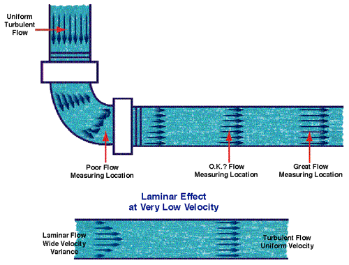
To insure the best accuracy possible, the flow profile of the fluid to be measured must be as uniform as possible across the pipe or duct, and the velocity must be high enough to ensure turbulent flow. With uniform turbulent flow, almost any placement of a differential pressure or turbine device across the pipe or duct diameter will give a good representation of the average fluid velocity. As the flow profile loses uniformity (close to an elbow or tee, for example), error is introduced since the device placement might be in a region with a higher or lower velocity than the actual average. The same effect can occur if the velocity slows enough to create laminar flow. The flow profile illustration to the right indicates these effects.
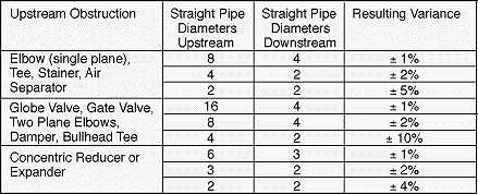
Robert Benedict’s Fundamentals of Temperature, Pressure, and Flow Measurement cites several studies in the International Journal of Heat and Fluid Flow which demonstrate that about 8 upstream diameters of straight pipe after an elbow are sufficient to produce ±1 percent variance with an orifice meter. Reduction of straight pipe to only 4 diameters yields ±2 percent variance if a constant correction factor of 0.98 is applied to the orifice discharge coefficient. In either case, the downstream straight pipe need only be two to four pipe diameters in length. If the upstream problem is more obstructive than a simple elbow (a valve, perhaps, or a bullhead tee), the lengths of straight pipe needed are closer to 16 diameters upstream for ±1 percent, and 8 diameters for ±2 percent. Table 1 is derived from Benedict’s work, and is valid for any fluid in fully developed turbulent flow. In typical HVAC applications, turbulence is pretty certain. If in doubt, check to see if the flow in question has a product of velocity (V, feet per minute) and the equivalent circular pipe or duct diameter (D, in inches) that meets the following criteria:
For Air, V x D > 650
For Water, V x D > 20
For Steam, V x D > 110
In summary, even if there isn’t enough straight pipe or duct to meet the manufacturer’s requirements, it is often possible to get a “pretty good” reading anyway, and the results will be very repeatable even if they’re off by a few percent.

Table 1: Effects of Upstream Obstructions on Flow Profiles. Add the “Resulting Variance” to the manufacturer’s stated accuracy to get an idea of expected behavior of a flow transmitter when the published straight pipe (or duct) length exceeds those in the table. While we cannot guarantee these figures for every application, they are valid for most HVAC/R flow ranges, and may even be improved upon with the use of straightening vanes or honeycomb flow straighteners.


