The various devices comprising a building automation network are either connected by cables or talk wirelessly to each other, or possibly a combination of both. In Networking 101, we are going to concentrate on network devices connected by cables. Let’s take a look at the different types of network cables typically encountered in building automation networks.
Network Cables
The most common type of network cable used in building automation networks is the “twisted pair” cable. Two wires are twisted around and around each other at a uniform number of twists per inch to form the “twisted pair”: 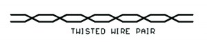 Why twisted pair cable? Without going into a lot of technical detail, let’s just say that with the proper type of transmitters and receivers using twisted pair cable greatly reduces noise pickup from noise sources such as motors, fluorescent lights, and radio stations. This results in more reliable communications with less corrupted data and retransmissions.
Not all twisted pair cables are created equal. There are electrical characteristics such as resistance and capacitance per foot that vary between different brands and models of twisted pair cable. Generally the lower the resistance and capacitance of twisted pair cable, the better it performs in networks.
It’s a good idea to select a network cable that’s specifically recommended by the manufacturer for use in your type of network. If network-specific cable is not available, substitutions can be made. If the resistance and capacitance per foot of the proposed substitute cable is as low as or lower than the recommended cable, the substitute cable should be acceptable.
Some styles of network cable are available with or without a metallic shield around the outside of the wires. Shielded cable generally helps with reducing noise pickup, but the cable will cost more.
Now let’s get more specific about the types of physical layers typically found in building automation networks…
RS-485
RS-485 is used extensively in building automation networks. Modbus RTU, JCI Metasys N2, and BACnet MSTP protocols all use RS-485.
RS-485 uses a single twisted-pair to send the data. It also uses a third “reference wire” in addition to the twisted pair. There is debate among users as to whether the reference wire is always needed, and some devices do not include a terminal for connecting a reference wire. But to be safe it’s always best to include it in the cable: 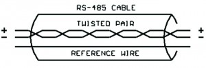 RS-485 devices typically use screw terminals for connecting to the cable.
The two wires of the twisted-pair do have a polarity assigned to them. The same wire of the pair must be connected to the RS-485 “+” terminal of all the devices on the network. If an RS-485 device is connected to the network with the “+” and “-“ wires attached backwards, it will not talk on the network!
RS-485 cable should be run as one continuous “trunk line.” The RS-485 standard specifies that as many as 32 devices can share the same trunk line, and the line can be as long as 4000 feet.
It is bad practice to “tee” into the middle of an RS-485 cable and run a “stub” line off to another RS-485 device:
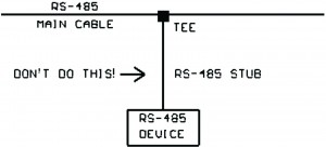
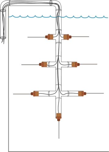
Instead, the RS-485 line should be daisy-chained to each device on the line like this: 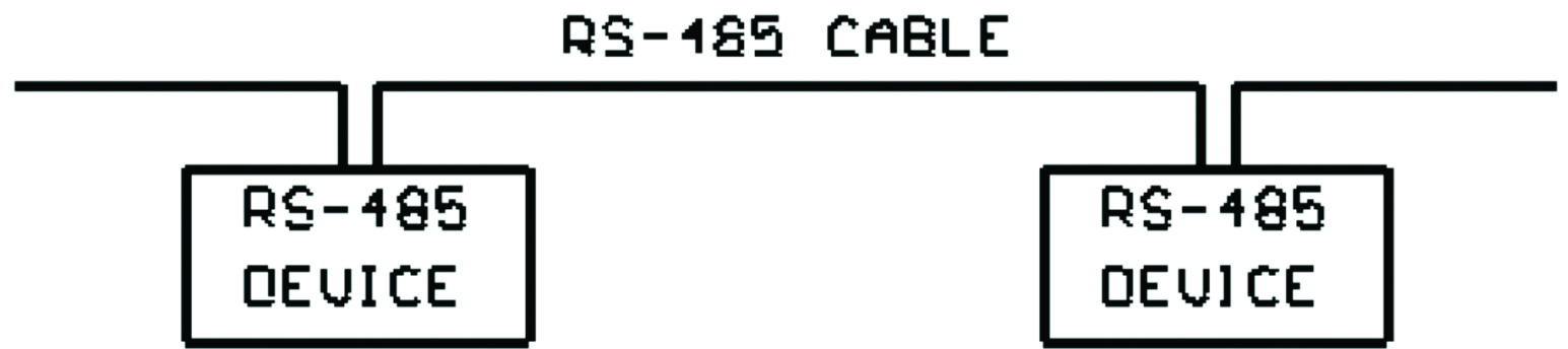
If an RS-485 cable needs to be longer than 4000 feet a “repeater” module can be inserted in the middle of the cable run. The repeater will refresh the electrical signals and allow for longer runs.
You can also expand an RS-485 network to more than 32 devices by creating multiple sub-networks, each with its own cable, and connecting the sub-networks together with a “bridge” or “router” device. A bridge or router will have two or more separate RS-485 electrical ports. Each port on the bridge/router connects into one of the sub-networks and data can then flow between the sub-networks:
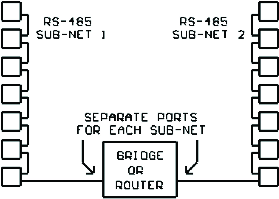 A “Bridge” forwards all the traffic on either sub-network across to the other sub-network.
A “Router” has the capability to learn (or to be told through a user-generated lookup table) which devices reside on each sub-network. Now if two devices on the same sub-network are talking, the conversation is not passed to the other sub-network. This eases overall network traffic congestion.
FT-10 “Free Topology” (Lonworks)
The FT-10 “Free Topology” physical layer was invented by Echelon Corporation as part of their Lonworks networking technology.
Similar to RS-485, FT-10 uses a single twisted pair to carry the data, but FT-10 does not use a third “reference wire”:
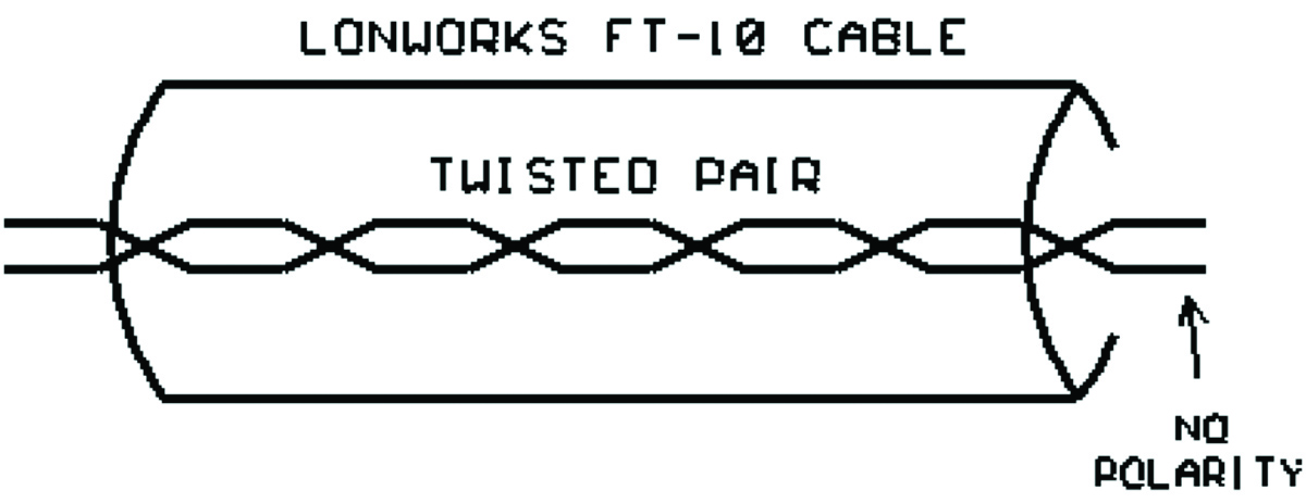 The FT-10 twisted pair has no polarity – the wires can be attached to each Lonworks device without worrying about which wire is “+” and which is “-“.
Like RS-485 devices, Lonworks FT-10 devices also typically use screw terminals to connect to the network cable.
FT-10 is much more relaxed as to how the cables can be arranged – you can pretty much wire different FT-10 network segments together any way you want to. You can “tee” into an FT-10 line with a “stub” headed in another direction, or you can make a “star” with a center point and multiple lines radiating out from it:
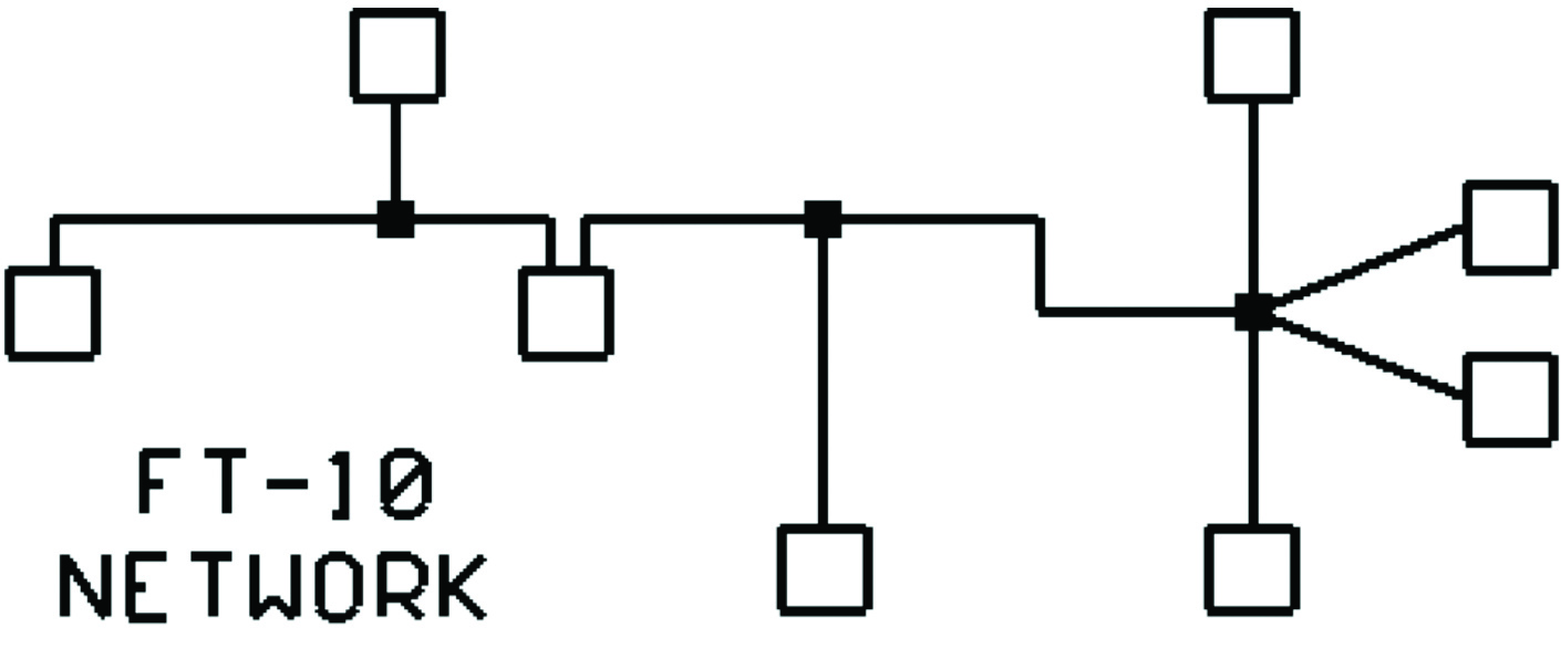 Lonworks FT-10 documentation recommends that the total cable run be no longer than 1640 feet and you put no more than 64 devices on a network.
As was the case with RS-485, you can extend the FT-10 cable distance with an FT-10 repeater. You can also extend beyond 64 devices by creating sub-networks and connecting them together with an FT-10 bridge or router.
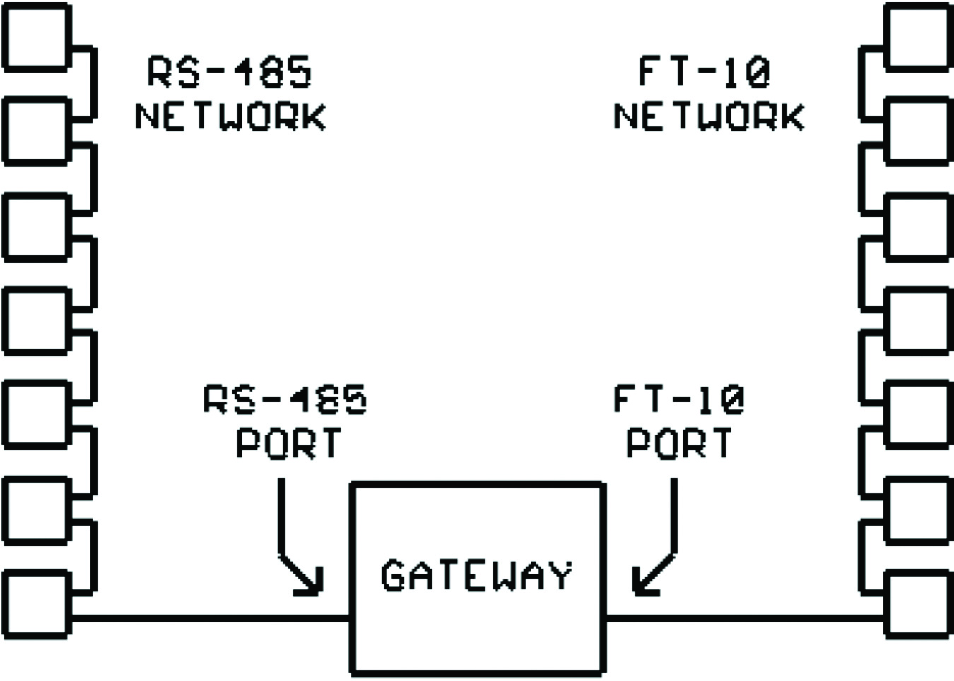
Please note that even though RS-485 and FT-10 both use a single twisted pair to carry the data signals, they are totally incompatible electrically! You cannot ever tie an RS-485 network cable directly to an FT-10 network cable.
If you want to communicate between an RS-485 network and an FT-10 network, you must use a “Gateway” device which has an RS-485 port on one side and an FT-10 port on the other side:
 Ethernet
Ethernet was invented back in the 1970s by Xerox and is extremely popular in the Information Technology world. BACnet IP and Modbus TCP protocols use the Ethernet physical layer.
There are several different versions of “Ethernet” networks, but the two we deal with in building automation are the 10BASE-T and 100BASE-T versions. The only significant difference is the speeds. 10BASE-T runs at 10M (10 million bits per second). 100BASE-T runs at 100M (100 million bits per second).
10BASE-T and 100BASE-T devices can be mixed on a network. If a 100BASE-T device needs to talk to a 10BASE-T device, it simply drops its speed to the 10BASE-T rate temporarily.
The two styles of Ethernet cables you’re likely to encounter in building automation are designated as CAT5 (Category 5) and CAT5e (Category 5 Enhanced). Both cable styles can be used with either 10BASE-T or 100BASE-T, but CAT5e cable gives superior performance.
The 10/100BASE-T cable contains four twisted pairs, but only two of them are used to carry the data: 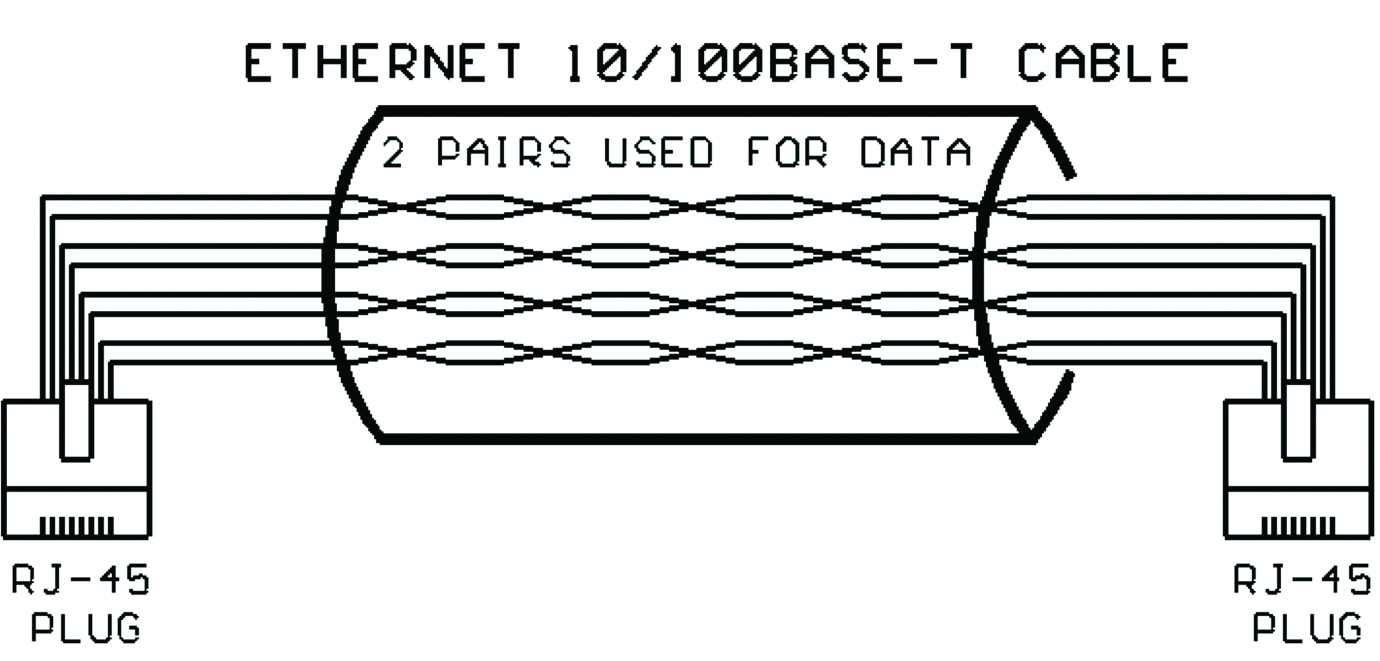 The other two twisted pairs may be left unused or used for some other purpose.
Standard length off-the-shelf 10/100BASE-T cables typically come with RJ-45 plugs pre-installed on the ends of the cable. RJ-45 plugs look like modular telephone plugs except they are wider and have positions for 8 connections. If you need to make a custom length 10/100BASE-T cable, you can buy a bag of loose RJ-45 plugs and a special wire stripper/crimper tool and attach RJ-45 plugs yourself (but it is a bit tedious to do).
Unlike RS-485 and FT-10, you can only connect two devices with a 10/100BASE-T cable! And the recommended maximum cable length is only 330 feet. So how are we able to network many devices together? The answer is in the use of Ethernet cable-sharing devices such as “hubs” and “switches.”
These hubs and switches have multiple RJ-45 data jacks for plugging in Ethernet cables. They are used to build out an Ethernet network “like a tree”:
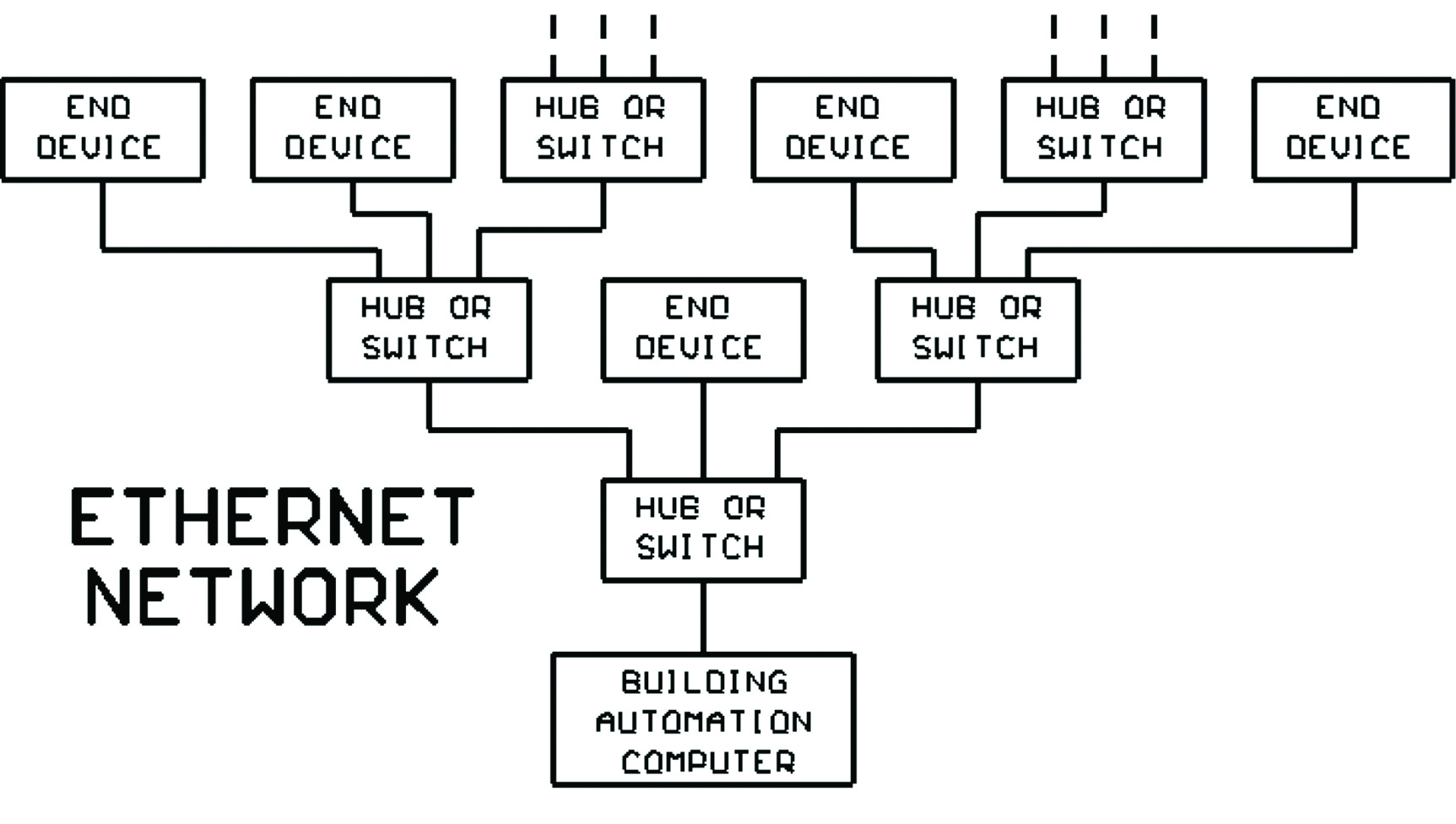 An Ethernet ‘Hub” forwards everything it receives on any port out all the other ports on the hub. So if an Ethernet network is built using all hubs, every end device on the network must listen to every conversation on the network whether it’s involved or not. This creates a lot of unnecessary traffic and slows down the operation of the network.
An Ethernet “Switch” learns where the different end-devices are located in the network and restricts the traffic flow to only those network segments that are needed to reach the specified end device. This greatly reduces unnecessary traffic on the network and speeds up response time.
An Ethernet “Router” is used to connect multiple Local Area Networks (LANs) together to form a Wide Area Network (WAN). There are also Ethernet “Gateways” to connect Ethernet networks to RS-485 or FT-10 networks.
RS-232
RS-232 is a physical communications layer that is used for making point-to-point connections between 2 pieces of equipment.
You may find that some network devices include an RS-232 port for connecting to a computer to perform device configuration. This RS-232 port is not for the network connection, only for configuring the device prior to using it on a network.
RS-232 ports on older equipment used 25-pin connectors like this: 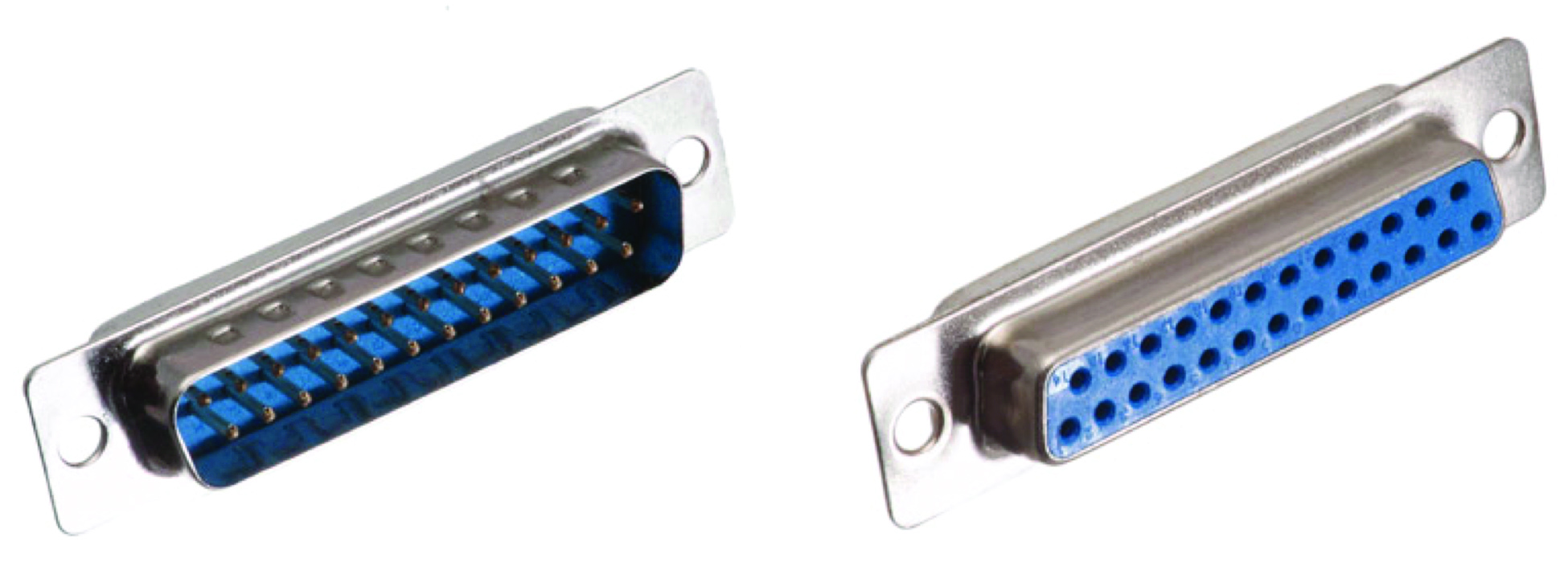 Modern equipment providing RS-232 ports use 9-pin connectors like this:
 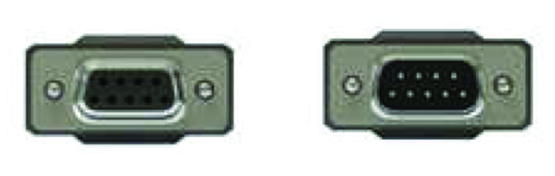 The connectors come in both male and female versions, so when connecting two pieces of equipment you must the sure that the cable has the correct gender connectors.
A “normal” RS-232 cable will have a male connector on one end and a female connector on the other end with “straight-through” wiring (pin 1 connects to pin 1, pin 2 connects to pin 2, etc.). But sometimes a custom cable must be purchased or fabricated with male-male or female-female connectors and possibly with crossed wiring between the pins. The details of these special RS-232 cables are beyond Networking 101.