If you’re involved with building automation systems you know (unless you’ve been living under a rock like the guy in that insurance commercial) that the modern trend is to connect all your building controls together on networks. Networks make it easy to add or move control nodes as your building control needs change since the nodes all connect to the network in a consistent, simple manner.
Obviously the various monitoring and control nodes on a building automation network must be able to talk to each other over some sort of medium. Both wired and wireless networks (or a hybrid combination of the two) are possible. Almost all wired networks deployed for building automation use twisted-pair communications cables. There are three popular types of twisted-pair communication schemes in use:
| RS-485 | (BACnet MSTP, Modbus RTU, Metasys N2 protocols) |
| FT-10 Free Topology | (Lontalk protocol) |
| Ethernet | (BACnet IP, Modbus TCP protocols) |
Today we are going to discuss the RS-485 twisted pair communications scheme and the significance of a little component called the “network termination resistor.”
A twisted-pair communications cable, as the name implies, has two insulated signal conductors twisted around and around each other at a consistent (N turns per inch) twist rate. Twisting the insulated conductors around each other reduces noise radiating outward and also improves immunity to external noise pickup. Twisted pairs are especially beneficial when used with a certain type of transmitter and receiver hardware known as “differential” signaling hardware which is used in RS-485 communications.
Twisted-pair communications cables have an electrical property called “characteristic impedance.” A cable’s characteristic impedance could be simply described as “how the cable looks to a high speed data pulse traveling down the cable” without getting into a lot of electromagnetic theory.
A cable’s characteristic impedance is expressed in units called “ohms.” You don’t need to worry about what an ohm is for purposes of this article.
Those of you who have some electrical experience are thinking that maybe you can measure the characteristic impedance of a cable by attaching your DC ohmmeter to the conductors and taking a reading. Sorry, it won’t work! You’ll just measure infinite resistance or pretty close to it. A cable “looks different” to a high speed data pulse than it does to a steady state DC voltage applied to it.
Sometimes a data cable will have its characteristic impedance stamped on the cable jacket, sometimes not. Most twisted-pair data cables will have an impedance somewhere between 100 and 150 ohms. A data cable specifically marked for RS-485 applications will have a characteristic impedance fairly close to 120 ohms.
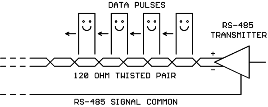
Now as a data pulse travels down a twisted-pair data cable, you might say it “gets used to” the cable’s characteristic impedance. As long as the cable’s impedance doesn’t change unexpectedly the data pulses happily propagate along:
*** RS-485 WIRING TIP #1:
RS-485 will sometimes work with only the twisted pair connected between nodes, but you have a much better chance of making it work reliably if you also run the RS-485 Signal Common wire between the nodes. This topic really deserves its own tech article and we aren’t going to delve into it any deeper today! Just remember to provide the signal common hookup whenever possible.
Now RS-485 architecture allows many nodes to co-exist on a communications cable. So the transmitted data pulses will be read by all attached nodes. To keep from loading the transmitter too heavily, each RS-485 receiver has a high-impedance (12000-96000 ohm) input.
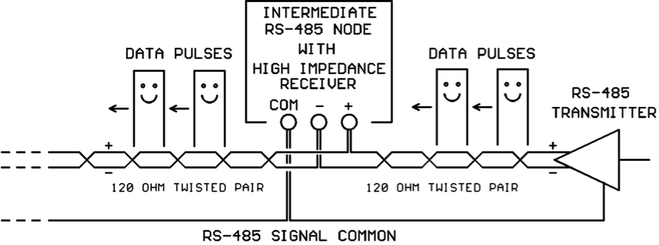
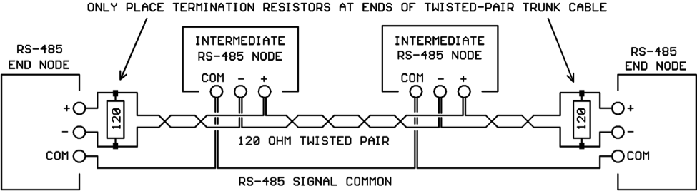
At each intermediate node (nodes not connected at the ends of the cable), the data pulses arrive on a 120 ohm twisted pair and leave on a 120 ohm twisted pair. The high impedance receiver inside the node does not load down the line, and so the data pulses happily travel on to the next node on the line:
*** RS-485 WIRING TIP #2:
For intermediate nodes on an RS-485 line, DO NOT make “stubs” that “tee” into the main twisted-pair trunk line! Run the incoming pair and the outgoing pair directly to the screws on the intermediate node as shown above.
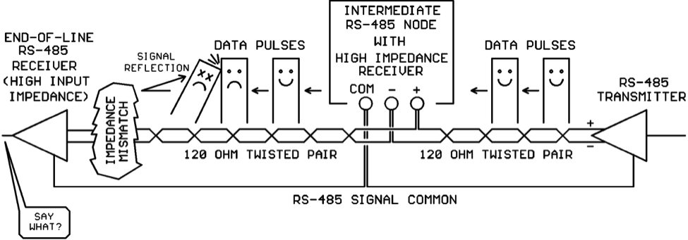
So our data pulses are happily traveling down the twisted-pair communications cable being read by each intermediate node on the line until they come “to the end of the line” (cue ominous background music!).
At the end of the line, the data pulses traveling on the 120 ohm twisted pair suddenly encounter the high-impedance input of the last receiver on the line. This is known in transmission-line theory as “impedance mismatch” and it isn’t good!
When the data pulses hit the impedance mismatch at the end of the twisted pair, some of the energy in the pulses is literally reflected backwards up the line where it collides with the other data pulses. If the energy reflections are bad enough, the RS-485 receiver may not be able to interpret the data pulses correctly:
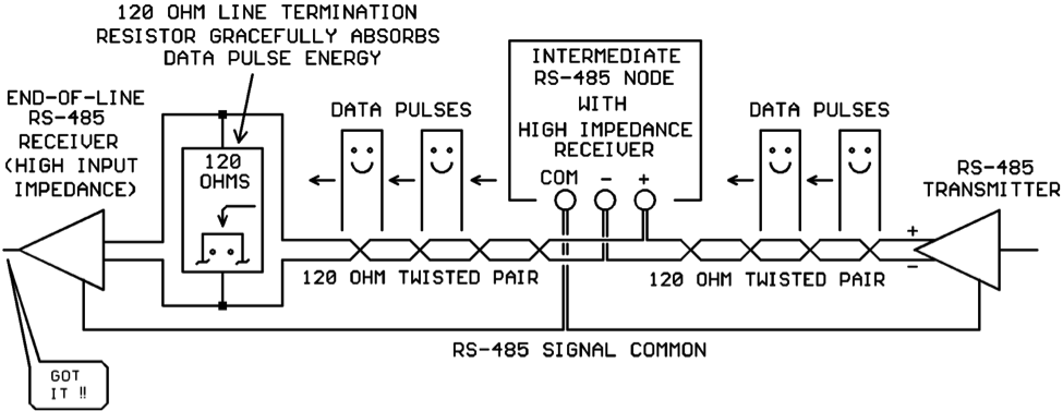
Obviously we’re going to have to do something about the impedance mismatch at the end of the line! Fortunately, there is an inexpensive fix for this. A small electrical component (a 120 ohm resistor) can be purchased and wired across the ends of the twisted pair. Then, when the data pulses get to the end of the line they continue to see an impedance of 120 ohms due to the presence of the resistor. Instead of reflecting, the energy travels into the 120 ohm resistor where it is converted into miniscule amounts of heat, and the data pulses fade away gracefully:
The 120 ohm resistors are inexpensive and easily obtained from distributors.
*** RS-485 WIRING TIP #3:
Only place 120 ohm termination resistors at the ENDS of the RS-485 twisted-pair cable. Do not install termination resistors at any of the intermediate RS-485 nodes:
Conclusions
120 ohm network termination resistors placed at the ends of an RS-485 twisted-pair communications line help to eliminate data pulse signal reflections that can corrupt the data on the line.
We have heard anecdotal stories about how adding termination resistors did not help, and in some cases made matters worse! That’s always possible, real-world network installations don’t always follow the assumptions made for a “typical” installation. But on the whole the termination resistors will help network performance more often than they will hurt it.
Remember, network termination resistors are yet another tool in your network installation/troubleshooting toolkit. They are not a cure-all for all network problems. Keep a bag handy, and use them when it helps!


Thank you for sharing the article. I highly enjoyed it and also bookmarked it for future reference.
Great write up, sending this to people a lot when they ask me why I keep shouting at them to install the EOL resistors.
FYI, in my experience the only time resistors “make it worse” was when something else was catastrophically wrong, like the shield drain not being grounded even though the MSTP wire is going into multiple VFD’s. Or standard 18/2 used instead of low-cap twisted pair. And even then, I think its debatable if its really worse, more like just not better. After the other installation mistakes were corrected, it’ll always be better with the resistors installed.