In the current economic times it can be difficult to convince a client that it is necessary to remove a working valve just to change out the pneumatic actuator controlling it. Re-piping and draining the system alone means down time and extra labor that probably isn’t in the budget. The obvious solution is to leave that valve there and upgrade the actuator.
There are companies out there, like Belimo, which have an entire section of business dedicated to retrofitting other company’s old valves though there are limitations to this. They mainly focus on the most common valve lines for the major valve manufactures.
Here at Kele we work daily with many of the manufactures that have been making valves that are still working away after 30 years of service. All it takes is a valve body model number and we can do the rest. Though sometimes the valves are just too old and the designs have changed so much that there is no way to mount a modern actuator on it; more often than not we can offer an option.
If you have a situation where you want to try to retrofit but don’t know where to begin, start by getting as much info from the parts on sight as possible. First is the valve number, which is hopefully on the tag that no one has torn off in thirty years. If there is no tag (very common) write down all of the markings on the body itself and if possible take a picture. While you at it take down all of the info off of the actuator as well.
It is important to note that it is never possible to choose a new actuator for a valve based on the old actuator number when going from pneumatic to electronic. This can only be done with the valve number. The info on the actuator is helpful however, and can give up clues to things like normally open or normally closed. Plus if an old valve with no tag has an old Barber Colman actuator on it that will at least point us in the right direction.
As you can probably tell, this really isn’t an exact science but it is a viable option. We are always happy to try, especially if it means saving you time and money. So, next time you are staring at an ancient valve and don’t know where to start, give us a call.
 One of the great perks of working for the nation’s leading supplier of building automation products is field trips to locations where there are interesting applications for our products.
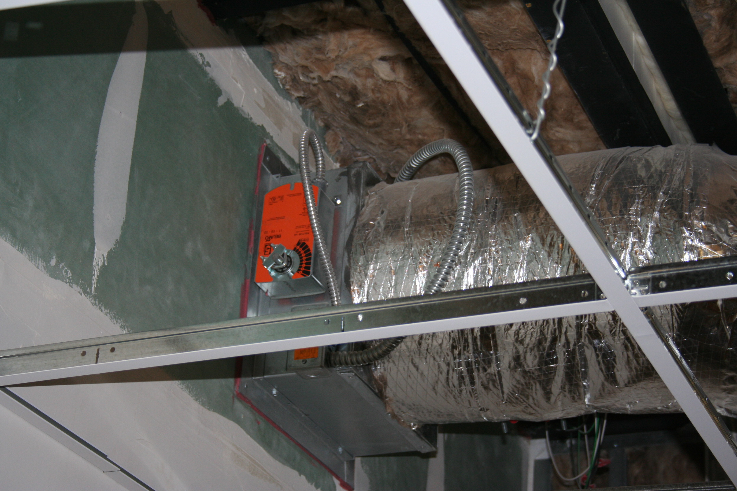 Belimo Actuator
 Setra Room Pressure
 Beginnings of a Modular Hospital
 Module Being Lifted into Place
 All Modules in Place
 View from the Top
 Well, when it comes to intriguing new applications for Kele’s peripherals in building automation systems, I just can’t help being nosey.
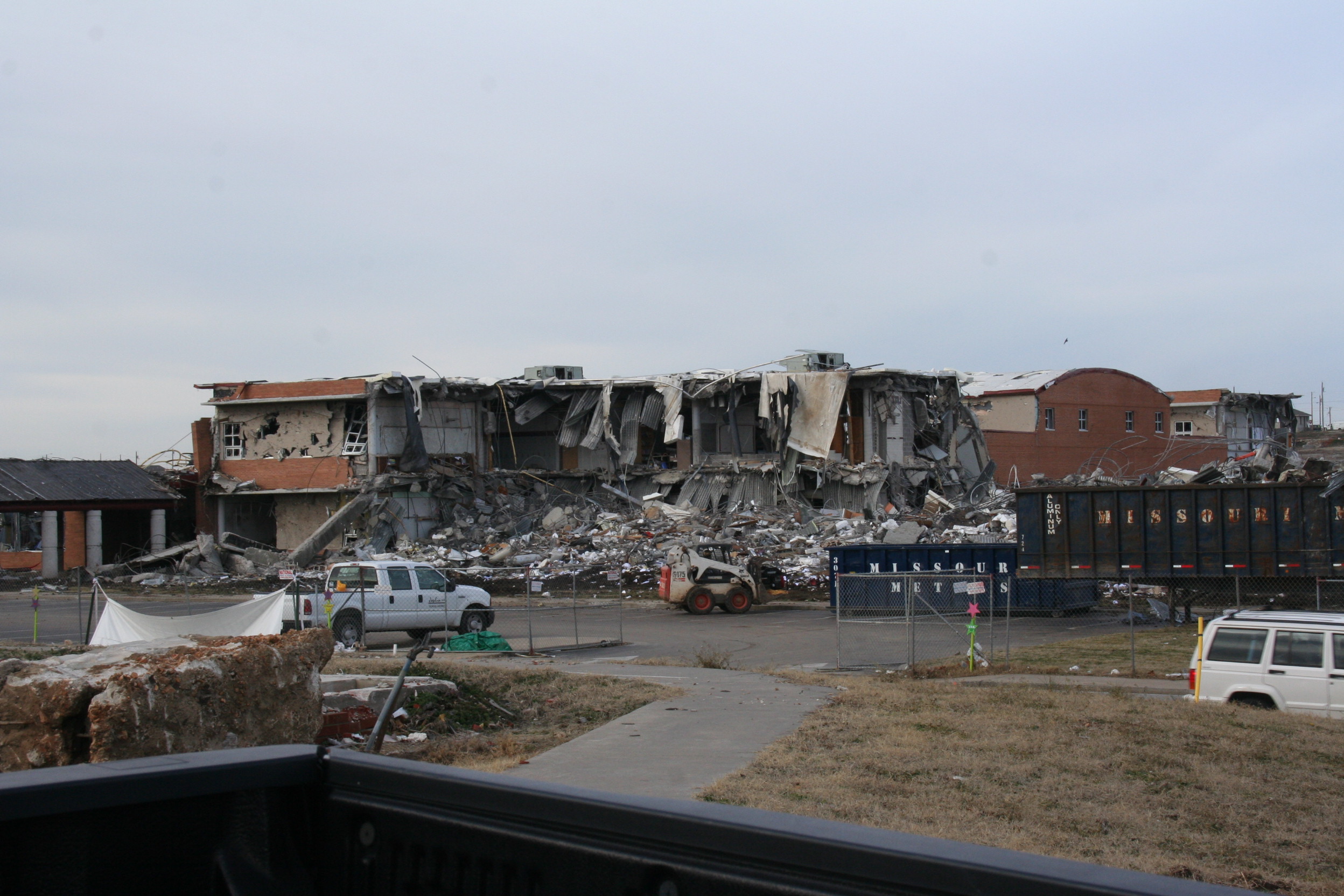 High School
 Now a Vacant Lot


