Reprinted from Summer 1999 Insights
In the last edition of 20/20 Insights we covered the use of explosion proof construction to prevent a source of ignition from coming in contact with a room full of fuel and air. Strong enclosures with threaded or flanged covers can confine explosive forces within themselves and cool the escaping gases enough to prevent ignition of the surrounding atmosphere.Wouldn’t it be even better to prevent any explosion at all?
Intrinsically safe systems are designed to do just that. Remember that even if the ideally explosive mixture of fuel and air exists, an ignition source of sufficient energy and duration is required to light it up. Intrinsically safe design limits the available release of energy in the hazardous area to a level well below the minimum ignition energy of the worst-case gas mixture. It also maintains this limiting function in the event of two simultaneous worst-case faults. Since this type of protection is very fail-safe and requires no enclosure maintenance, most engineers (and property insurance carriers) consider it to be even safer than explosion proof construction. Surprisingly, it is usually less expensive to boot!
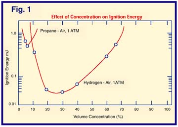
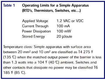
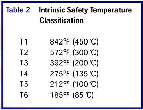
How does it work? First of all, let’s consider a room filled with hydrogen and air in exactly the best proportion for ignition (about 30 percent hydrogen by volume – see Figure 1). This mixture takes an instantaneous release of about 20 mJ in order to start burning, or else its temperature must be raised above the autoignition temperature of hydrogen (932 deg F or 500 deg C). For electrical devices we wish to place in this room, the amount of stored energy and the rate at which it can be released under worst-case conditions must be kept below these critical levels, and the surface temperature (see Table 2 for ratings) must be kept below the autoignition temperature. If these conditions are met (to the satisfaction of UL, FM, CSA, BASEEFA, etc… ), then the device may be listed and labeled as intrinsically safe. This means that, with a properly applied safety barrier, cabling and ground, it cannot start a fire even under the worst-case conditions. There is one subset of such intrinsically safe devices that can be used without a listing or label (although a barrier, proper cabling and ground are still required). These are designated “simple apparatus” and are a group of things that obviously neither produce nor store any energy (RTD’s, thermistors, switches, and a few others). They may be used as if they did have a label, as long as the operating limitations shown in Table 1 are strictly adhered to.
 So, if we have an RTD and an intrinsically safe temperature transmitter in a hazardous location, can we wire them up to our controller and power supply in the safe area and turn them on? Not yet! Three more steps are needed first. While the devices in the hazardous area cannot ignite the gas mixture on their own, the controller and power supply in the safe area may each be capable of transmitting enough energy through the wires into the hazardous area to do the job anyway! An intrinsic safety barrier will prevent this, and is required for every intrinsically safe device (except listed self-contained battery powered units). Barriers range from simple to sophisticated, but they all use fail-safe components to limit the voltage and current that can be passed through them even in the event of worst-case wiring errors. For example, suppose someone in the safe area accidentally hooks 240 VAC up to our temperature transmitter signal lines, and one of the lines is frayed enough at the transmitter to cause an arc at that voltage. Without an intrinsic safety barrier, there may not be enough evidence left to figure out what happened. However, a barrier rated for the atmosphere, cabling, and its field device will save the day even under these circumstances.
 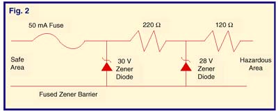 Figure 2 illustrates a simple zener diode barrier circuit. A high voltage at the safe side terminals will cause the zener diode to draw a high current and blow the input fuse. The series resistors limit the current to the hazardous side. Barriers are also rated for how much capacitance and inductance are allowed on the hazardous side.
This leads us into the cabling between the hazardous area device and its barrier. If the cable is very long and has a high capacitance, it could possibly store enough energy to cause an ignition in the event of a wiring fault. It must be checked against the rating of the barrier. If the field device (the transmitter in our example) has a high capacitance, the combined capacitance of the cable and device must be less than the barrier rating. Cable and device inductance are treated in the same manner.
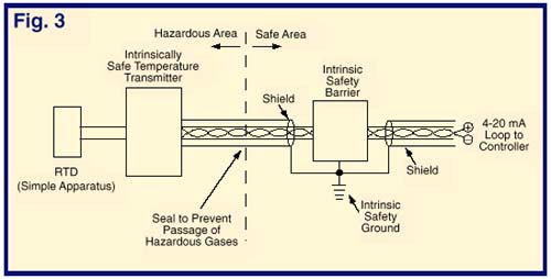
 The final factor to consider is grounding. What good is all this built-in electronic safety if a nearby lightning strike raises the ground potential a couple of thousand volts above the potential of the cable shield in our hazardous area? The resulting arc from the shield to ground can be every bit as effective as a butane lighter in touching off an explosion, and we needn’t have bothered with using intrinsically safe products. An intrinsic safety ground, bonded to the earth ground, is the last essential link that makes the system work. Normally provided at the barrier location, it keeps the cable shields at or near the same potential as the earth, even as that value moves around during storms.
Once it is all together, as shown in Figure 3, the benefits of an intrinsically safe system are many. There is no need to power systems down and”safe” the atmosphere for maintenance. Calibrate, adjust, even swap out bad parts with the system turned on and the atmosphere at its worst – a properly designed system cannot release enough energy to do any damage.