This past weekend, we were just back from a trip to market, and my wife was busy stowing the fruits, veggies, oils, kimchi, and spices. I was doing my usual chore of qualifying and sorting the plastic shopping bags as to fitness for cat litter duty, kitchen waste duty, and “other,” based on leakage potential. I’m sure all of you engineers out there know the drill, so I won’t belabor it. Since this is a simple test routine that requires very little thought (as long as the cat’s asleep), my mind wandered into the realm of strange electrical anomalies, as my mind tends to do at such times…
Having just finished up researching an article on instrument isolation practices for conditions in which “ground” may not be the safest place to touch during a lightning storm, I got to thinking of other instances in which the normal means of protecting electrical circuits can be outflanked by Mother Nature. I recalled one episode of returned product from a customer whose 30A relay contacts, socket, and screw terminals had all obviously been subjected to extremely high current. The relay armature had melted and burned violently, while the contacts were welded together. The whole thing was a black, charred, mess. We were unable to reproduce such damage with the largest load that we could throw on it at the time. We could make it pop and sizzle, and eventually it would fail at 60A – but not in a blaze of glory like the ones returned to us.
Why did the customer return them to us in the first place, if they had obviously been subjected to fault-level currents, which would certainly not be a warranty issue? The 20A circuit breaker upstream of the relays did not trip during this event! In fact, the circuit that appears to have unleashed all of its fury on the poor little relay remained intact and continued to power other, non-controlled loads as if nothing had happened. Our customer wanted us to help determine the trouble – and more importantly, give him some advice to keep it from happening again.
After several rounds of questions and the review of e-mailed pictures, building drawings, and wiring diagrams, we were finally able to determine that this relay was controlling a lighting circuit. It was composed of one long row of fluorescent fixtures at the ceiling level of a warehouse, and at the end of the row it poked out through the wall and also powered one outdoor area light that was mounted on the uppermost corner of the building. One more question brought closure. Was there a thunderstorm that day?
The energy of a lightning strike is immense, we all know that. What was unusual about this situation was that the energy of the strike originated at the end of the circuit, traveled back upstream toward the power source, and caused the control relay to become the fuse that saved the rest of the equipment on the circuit from disaster! In burning the contacts and armature of the relay, enough energy was expended that the next device upstream (a 20A circuit breaker) didn’t need to operate – and the remainder of the lighting branches that were tapped off upstream of the relay suffered no damage. Remember, lightning doesn’t always send us trouble down the electrical wires from the source – sometimes it sneaks in the back way.
We’ve seen some strange ones during our long careers, and we’ll post ‘em here from time to time for everyone’s enjoyment (engineering enjoyment, that is). Perhaps it’ll help one day when one of our customers runs into an electrical problem that just doesn’t seem to follow the rules.
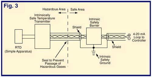
 So, if we have an RTD and an intrinsically safe temperature transmitter in a hazardous location, can we wire them up to our controller and power supply in the safe area and turn them on? Not yet! Three more steps are needed first. While the devices in the hazardous area cannot ignite the gas mixture on their own, the controller and power supply in the safe area may each be capable of transmitting enough energy through the wires into the hazardous area to do the job anyway! An
 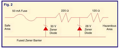 Figure 2 illustrates a simple zener diode barrier circuit. A high voltage at the safe side terminals will cause the zener diode to draw a high current and blow the input fuse. The series resistors limit the current to the hazardous side. Barriers are also rated for how much capacitance and inductance are allowed on the hazardous side.
 The final factor to consider is grounding. What good is all this built-in electronic safety if a nearby lightning strike raises the ground potential a couple of thousand volts above the potential of the cable shield in our hazardous area? The resulting arc from the shield to ground can be every bit as effective as a butane lighter in touching off an explosion, and we needn’t have bothered with using intrinsically safe products. An intrinsic safety ground, bonded to the earth ground, is the last essential link that makes the system work. Normally provided at the barrier location, it keeps the cable shields at or near the same potential as the earth, even as that value moves around during storms.