Open an HVAC control panel, and you’re likely to find at least one relay mounted inside. Sometimes you find lots of relays! Even though relay technology has been around since the 1800s, there is still a need for relays in control panels.
What components make up a relay? How are relays typically shown in wiring diagrams? What functions can a relay perform? Stay tuned for some answers…
What Components Make Up A Relay?
A relay is constructed from the following components:
- Electromagnet (coil of wire with metal core)
- Armature (arm that moves when attracted by the energized electromagnet)
- Spring (keeps the armature retracted when the electromagnet is de-energized)
- Contact(s) (one or more electrical contacts that open or close when the armature moves)
- Electrical Terminals (so you can make connections to the electromagnet and contacts)
How Does It Work?
You might have built an electromagnet in high school science class and used it to pick up small metal objects. An electromagnet is a coil of wire wound around a metal core. When the coil of wire is hooked to an electrical power source and current flows through the coil, a magnetic field is produced which surrounds the coil and the core:
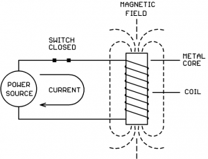
While the electromagnet is energized, any metal objects which come close will be physically pulled towards core.
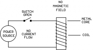
When the switch is opened, the current flow stops and the magnetic field disappears. When the magnetic field disappears, nearby metal objects are no longer attracted to the core:
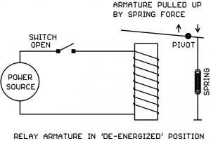
We now place a pivoted metal arm (armature) above the electromagnet, and we connect a spring to keep the armature pulled away from the electromagnet under “normal” (electromagnet de-energized) conditions:
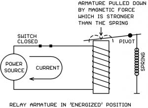
If we now energize the coil, the magnetic field will overcome the spring force and pull the armature down:
So… we have an armature which we can move up and down by de-energizing or energizing the electromagnet coil. What do we do with it?
We use the moving armature to open and close electrical contacts which are separate from the coil circuit. We can do it like this:
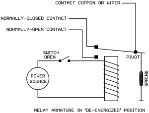
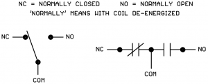
In this example, we’re using the metal armature itself as the “Common” or “Wiper” for a double-throw switch. The tip of the armature makes contact with one of two possible points depending on the position of the armature.
When the relay is de-energized, the armature is up and the wiper makes connection with the “Normally Closed” (NC) contact.
When the relay is energized, the armature is down and the wiper makes connection with the “Normally Open” (NO) relay contact:
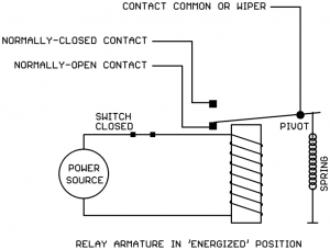
This example relay would be known as a “Single Pole, Double Throw” (SPDT) or “1 Pole, Double Throw” (1PDT) relay. It has one set of contacts (1 Pole) with both Normally Open and Normally Closed (Double Throw) connections.
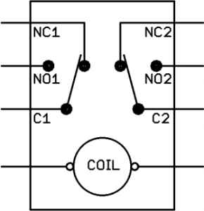
Relays can have more than one set of contacts (poles). In the next example, the metal armature is not part of the electrical circuit but instead moves a plastic connector that activates two sets of contacts:
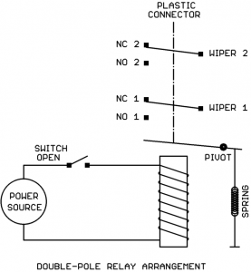
This would be known as a “Double Pole, Double Throw” (DPDT) or “2 Pole, Double Throw” (2PDT) relay.
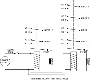
The number of poles (contact sets) can be expanded (3PDT relays, 4PDT relays etc.). Typically 4 poles is the largest relay we would see in an HVAC control panel. If you need more than 4 poles in a relay, you would probably use two relays with the coils wired together in parallel. Shown below are a DPDT relay and a 4PDT relay wired together to create 6PDT relay action:
Electrical Ratings of a Relay
The coil of a “classic” relay (no electronics) is typically rated for a specific voltage and either AC or DC operation but not both.
There are some modern relays (like Functional Devices “Relay In A Box”) that contain electronic circuits that allow the coil to operate over a range of voltages and either AC or DC operation.
If in doubt, the relay’s datasheet should clearly spell out the acceptable voltage range for the coil and whether it’s AC only, DC only, or AC/DC compatible.
Relay coils are generally tolerant of some variation in the coil voltage, a typical datasheet specification is 80% – 120% of rated coil voltage. So if a 24V transformer is “running a little hot” (putting out maybe 27V) or there is a bit of voltage drop in the coil connecting wires (maybe the coil is only getting 22V) the relay will still function just fine.
The relay contacts will have ratings for the maximum voltage allowed and the maximum current allowed. Sometimes there are multiple ratings depending on the type of load being switched (for a motor load sometimes the contacts are rated in horsepower for example). The circuit being switched by the contacts should not put more voltage or current on the contacts than allowed by the datasheet.
Relay Symbols Used in Wiring Diagrams
The relay coil may be drawn several different ways:
![]()
The relay contacts are typically shown one of two ways:
Relays go by several possible names on an electrical drawing:
‘R’ (not a great idea since resistors can have this designation too)
‘RL’ (better)
‘RLY’ (better still)
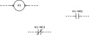
‘K’ (Where did this come from? We don’t know. But it’s widely used!)
If there are multiple relays, the name will be followed by a number or a letter as in RLY1, RLY2, RLY3 or RLYA, RLYB, RLYC. There might be a hyphen (-) between the name and number or letter too. There is no specific standard on how relays must be named.
Sometimes the relay is shown as a single assembly with coil and contacts arranged in a rectangle:
But sometimes the coil and the contacts are scattered around the drawing:
Relay Terminal Numbering
Unfortunately there does not seem to be a standard for the terminal numbering on relays.
Most of the relays we use in HVAC panels plug into a base socket. The pins/blades of the relay have assigned numbers and then the bases they plug into have assigned numbers on the screw terminals. If the same brand of relay and base are used together, the blade numbers usually match the terminal numbers on the base. If, however, different brands of relay and base are used together, the blade numbers may not match the base terminal numbers even though the two parts are physically compatible (example: IDEC SH3B-05 relay plugged into Omron PTF11A base). It’s a good idea to use the same brand of relay and base to avoid confusion.
Some electronic relays such as Functional Devices “Relay In A Box” have color-coded flying leads rather than screw terminals. Consult the device datasheet to determine the function of each color-coded lead.
Functions a Relay Can Perform
So what useful functions can a relay perform?
- Use a low voltage and/or low current signal (on the coil) to switch a large voltage and/or large current circuit (on the contacts).
- Use a DC signal (on the coil) to switch an AC circuit (on the contacts) or vice-versa.
- Use one signal (on the coil) to switch multiple circuits (multi-pole contacts).
- Invert the sense of a signal (using the Normally Closed contact).
- Use a signal from one circuit (on the coil) to switch another circuit (on the contacts) where the two circuits are not allowed to have any direct electrical connection.
- Use one signal (on the coil) to switch between two alternate loads (on the contacts).
- Various combinations of the above.
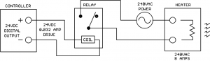
The example below demonstrates a relay performing a combination of several of the above functions. A low voltage, low current control signal from a controller is switching a high voltage, high current load on and off. The relay is also allowing a DC control signal to switch an AC load. There is also electrical isolation between the drive circuit and the load circuit so that the controller is protected from the high voltage 240V power source:
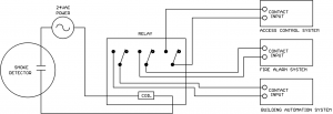
In the next scenario a smoke detector signal is being sent to three different systems simultaneously while maintaining isolation between the systems to make sure there is no unintended interaction between the systems:
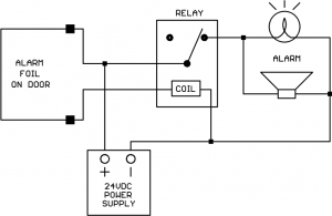
Here is an application where we want to reverse the sense of an electrical signal. We have a foil alarm loop glued to a glass door. When the foil is intact (current flowing through foil) we want to hold off the Alarm light and horn. When the foil is broken (current flow stops) we want to energize the Alarm light and horn. We can get the reverse action we want by using the Normally Closed contact on the relay:
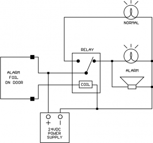
Let’s see how we can use both the N.O. and N.C. contacts to get “alternate action” between two loads. We decide that in addition to the ALARM light, we also want a NORMAL light for our alarm circuit that is on when the foil connection is intact. So we want the action of the NORMAL and ALARM lights to alternate, one or the other is on at any time, but never both at the same time. We can get this alternate action by adding the NORMAL light to the N.O. relay contact:
You may begin to see how versatile relays are. Even with all the high-tech electronics in control panels, relays will be with us for a long time to come. The operation is easy to understand and they can be used for many different applications.
Magnetic Latching Relays
There is a special class of relays known as “magnetic latching relays.” These relays contain one or more small permanent magnets which hold the armature in the last commanded position when the coil drive is removed. When a coil drive signal is applied, the magnetic field from the coil is stronger than the permanent magnets and can thus move the armature to the opposite position in spite of the permanent magnet’s presence.
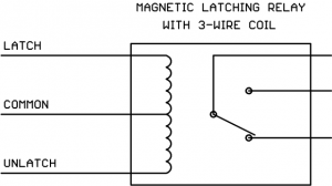
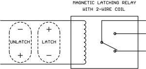
Magnetic latching relays must have two coil drive commands, Latch and Unlatch. Some relays accomplish this with two separate coil windings and two command leads:
Other magnetic latching relays have just two coil wires, but the polarity of the applied DC drive determines whether the command is Latch or Unlatch:
The Latch and Unlatch drive signals are typically meant to only be momentary, you normally would not leave either signal on the coil continuously.
Magnetic latching relays are frequently used in lighting circuits. One example is the popular General Electric RR7 lighting relay.
Wrap-Up
Some points to remember about relays:
- Make sure that the relay coil voltage and AC/DC rating matches the coil drive signal in the application circuit.
- Some relays are available with a “coil energized” light built in. If any troubleshooting has to be done on the panel, these lights can be very helpful.
- Some relays are available with a manual override button built in. If any troubleshooting has to be done on the panel, these override buttons can be very helpful.
- Make sure that the relay contact voltage and current ratings are at least as high as the volts and amps that will be applied by the application circuit. If possible, use contacts rated higher than the volts and amps that will be applied.
- If you need more poles than are available on one relay, you can use multiple relays with the coils connected in parallel.


This is very innovative and informative also useful Article. Thank you for sharing this Article.Thanks
Well written, informative.
Would like to see examples of relays used in electronic access control.
Usd of relays for controlling Magnetic locks, push bars(crash bar), electrified hinge..etc