“Resistance is futile, Buwhahaha” exclaimed the villain, rubbing his hands together in glee as our hero struggled to free himself from the ropes that bound him.
Yep, we’ve all seen those Grade B movies. Maybe in that situation resistance is futile, but in the world of electronics and HVAC controls resistance (electrical resistance) is very useful!
Designing selected values of resistance into the appropriate points of circuits lets us control the voltages and currents so the circuits perform as desired. The most popular forms of temperature sensors used in HVAC (RTDs and thermistors) operate by varying their electrical resistance as temperature changes. Resistors are also frequently used to convert the 4-20 mA signal from a transmitter into a 1-5V or 2-10V signal for controller inputs.
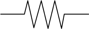
Electrical resistance is measured in units of Ohms. When resistance gets into values larger than 1000 ohms it may also be expressed in Kilohms or just ‘K’ for short (50K = 50,000 ohms). The symbol for resistance on electrical diagrams looks like this:
We’ll be measuring resistance with the Ohms function of our “multimeter” which can measure volts, current, resistance, and possibly other things too (frequency, capacitance, temperature with accessory probe, etc.). When the multimeter is set to the Ohms function, it may be referred to as an “ohmmeter.”
Plug the Meter Leads Into the Correct Meter Jacks
Shown below is a typical multimeter face layout. This is an actual meter Kele uses in our internal training classes. Note that your multimeter controls may be arranged somewhat differently or completely differently:
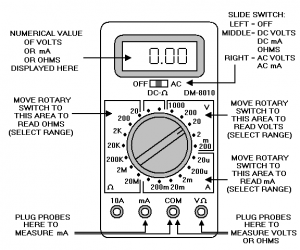
To read resistance, plug the black meter lead into the COM jack and plug the red meter lead into the V/ohm jack.
Set the Meter Selector to Ohms
The meter selector switch has different major areas for choosing whether you want to read voltage, current, resistance (ohms), or possibly other things. You need to move the selector switch to one of the positions in the Ohms area (left side of selector knob on our example meter).
Set Meter Range (Unless You Have an Auto-Ranging Meter)
Our example meter has different resistance ranges to choose from based on the maximum resistance you expect to measure. Always choose the smallest range that’s higher than the highest resistance you are expecting to measure. For example, if you are going to measure a resistance you think should be around 10K (10,000 ohms) then on the meter you would select the 20K range (because the 10K we want to check is higher than the next lower range which is 2K).
If you accidentally select a lower range than the resistance you are trying to measure, the meter won’t be damaged. You’ll get some kind of “overrange” indication on the display. This can vary from meter to meter. Sometimes it’s a row of horizontal dashes, sometimes it’s “OL” for overload, or maybe something completely different.
If your meter has an Auto-Ranging function you don’t have to worry about setting the range, the meter will figure it out for you. It will automatically step through the different ranges until it finds the lowest range that does not result in an over-range condition.
Auto-Ranging is very handy. The down side is that it can take the meter longer to display a final stable resistance reading because it has to trail-and-error each time to find the right range. A fixed-range meter manually set to the correct range will stabilize to a usable reading faster since it doesn’t have to experiment to find the correct range.
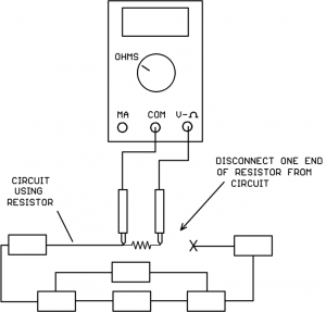
If the Resistor Is Connected In A Circuit, Disconnect At Least One End of the Resistor Before Taking A Measurement
If the resistor is connected in a circuit, at least one end of the resistor must be disconnected from the circuit before connecting the meter probes. If the resistor is left connected to other devices at both ends, you will be measuring the “equivalent resistance” of other circuit components in parallel with the resistor of interest. This will give a false reading that is lower than the actual resistor value.
It would also be a good idea to have the circuit powered down even though one end of the resistor is disconnected. The connected end of the resistor could be attached to a live voltage or current source and bad things could happen if the probes slipped.
Place the Meter Probes Across The Resistance To Be Measured
Remember to keep your fingers on the insulated probe handles, don’t touch the metal probe tips with your fingers. Your body is a resistor from hand-to-hand too, and if you grab both metal probe tips and try to read a high resistance value, your body resistance in parallel will introduce a measurement error.
If the display shows an over-range condition, just move the meter ohms selector to the next higher range and try again.
Special Notes On Temperature Sensor Resistance Measurements
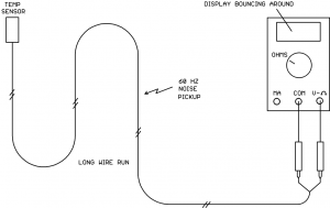
If you try to measure the resistance of a thermistor or RTD temperature sensor with a long wire run attached, you may find that the readings jump around on the display. This is caused by that long wire run acting as an antenna and picking up 60 Hz power line noise:
Some meters may have better noise filters than others, if you have more than one model meter available you might try them all to see which is better at noise rejection.
If the resistance value is jumping around, look for the minimum value that ever shows up on the display and the maximum value that ever shows up on the display. Chances are that the true resistance value will be approximately halfway between those two values.
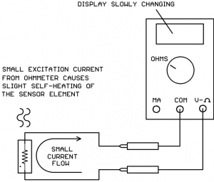
You might also notice that when you put the meter probes on the thermistor or RTD sensor, the resistance value starts to slowly move (up for RTDs, down for NTC thermistors). It’s unlikely (although remotely possible) that you have an unstable sensor, it’s more likely you are seeing the effects of self-heating in the sensor.
The ohmmeter passes a small current through the sensor resistance in order to measure it. This small current causes a slight heating of the sensor material. Since temperature sensors are specifically designed to give large resistance changes with temperature change, this self-heating shows up as a slow resistance change:
This is nothing to worry about and does not mean that the sensor is bad. The initial sensor resistance value (before self-heating takes effect) more accurately represents the temperature of the medium being measured by the sensor.
Temperature sensors with a small thermal mass and slow-moving media are more likely to exhibit self-heating effects than sensors with a large thermal mass and swiftly moving media. For example, a chip sensor sitting up in the air on two thin wires inside a wall-mount room housing will exhibit more self-heating effect than a duct sensor potted in the end of a metal tube placed in the moving air stream inside a duct.
Continuity Checks Using An Ohmmeter
Sometimes you simply want to know whether two points in a control panel or on a module terminal block are connected directly together. The ohmmeter is an excellent tool for doing continuity checks.
To perform a continuity check:
- Make sure the circuit is powered off.
- Place the ohmmeter probes on the two points to be checked.
- If the resistance is less than 1 ohm, the two points are very likely directly connected.
Why wouldn’t the resistance read zero ohms if the points were directly connected? Because all conductors icluding the ohmmeter test leads have some electrical resistance. You can prove this by shorting the ohmmeter test probes directly together and observing the display, it will show a non-zero (but very small) resistance value.
Take-Away Points
- If the resistance to be measured is mounted in a circuit, disconnect at least one end of the resistor from the circuit before measuring .
- Noise pickup on long wire runs can make the resistance value jump around on the meter. Look for the lowest and highest displayed values and take the midpoint between the two as the true value. Try a different meter to see if it has better noise filtering.
- Slowly changing temperature sensor resistance after connecting the meter is probably self-heating of the sensor element and not a bad sensor.
- When taking continuity measurements with an ohmmeter, don’t expect to read 0.00 ohms across two connected points. Any value less than 1 ohm is a good indication the points are directly connected.


Great article! Thank you