Some of you might remember that back in 1975 Paul Simon had a hit song entitled “50 Ways to Leave Your Lover.” Well, coming in a close second are the number of ways (47) that you can wire a 3-phase power meter incorrectly! In this article we’ll briefly discuss why there are so many ways to incorrectly wire a 3-phase power meter and how you can try to insure that your wiring is correct.
Cautionary Note
This article deals with the connections between power systems and the meters that monitor them. Hazardous, potentially lethal voltages are involved. See the Stayin Alive footnote at the end of this article for information on keeping yourself safe.
Six Different Inputs to Deal With
A 3-phase power meter has 6 different input signals which must be present and connected correctly in order to measure power accurately:
- There are 3 voltage inputs (we will refer to them as L1, L2, L3) which are connected to the three “hot” wires of the power system being monitored.
- There are 3 current inputs (we will refer to them as CTA, CTB, CTC) which are connected to 3 “Current Transformer” sensors (CTs). The CTs have holes through their centers and the L1, L2, L3 hot wires pass through the holes in the CTs. The CTs measure the currents flowing in the hot wires.
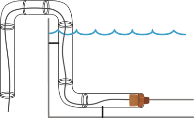
A picture may help to clarify our word description:
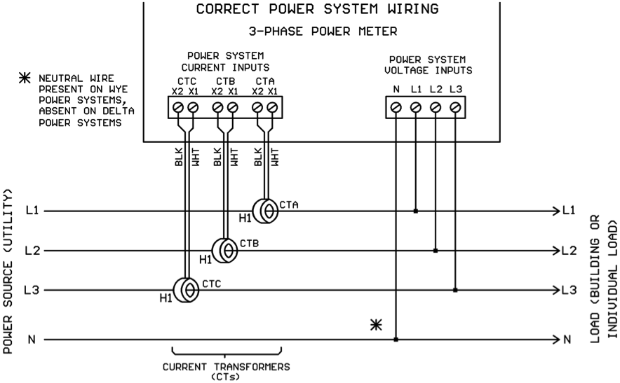
Note that a “Neutral” power wire is also shown on the drawing . This wire will be present on a 3-Phase Wye power system and absent on a 3-Phase Delta power system. This article is valid for both scenarios.
The L1/L2/L3 wiring is straightforward. A single wire is run from each “hot” wire to its corresponding L1/L2/L3 input terminal on the power meter. The CT installation and wiring are a bit more complex, however.
Note that each current transformer has two wires on its output which run to the power meter, and the power meter has 2 screws labeled “X1” and “X2” for each CT input. Normal convention is that the wires from the CT are colored white and black, and the white wire connects to the X1 screw while the black wire connects to the X2 screw.
The body of the CT has one side designated “H1” and the other side is “H2.” This could be done with labels or molded directly into the plastic CT body. The CT should be installed with the H1 side facing the power source and the H2 side facing the load.
How to Get It Wrong – Cross Wiring the CTs and L1/L2/L3 Wires
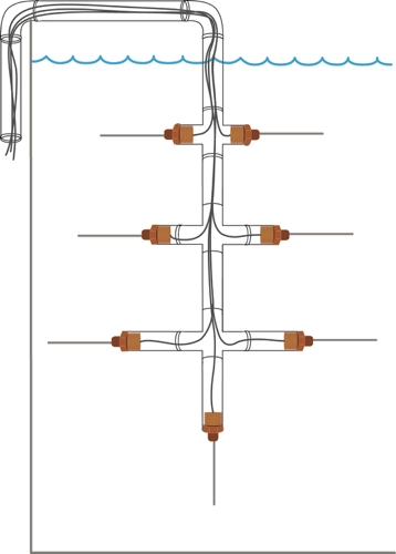
In the drawing below, current transformers CTB and CTC have been cross-wired with L2 and L3:
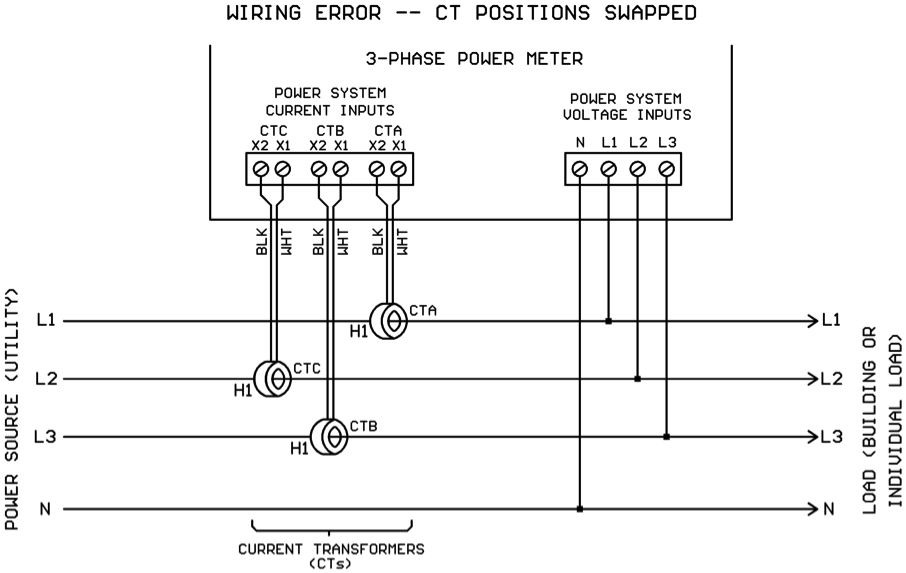
Note that CTB is around the L3 wire and CTC is around the L2 wire. In this scenario, the power meter will calculate Phase A power correctly, but Phase B power and Phase C power will both the incorrect, resulting in the total power also being incorrect.
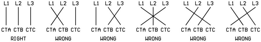
Here is a diagram showing the different ways that CTA, CTB, CTC can be paired with L1, L2, L3. Each diagonal line represents an incorrect cross-wiring between the CTs and hot wires:
How to Get It Wrong – Reversing the CT Polarities
In the drawing below, current transformer CTC has been installed over hot wire L3 with the “H1” side facing the load instead of the power source:
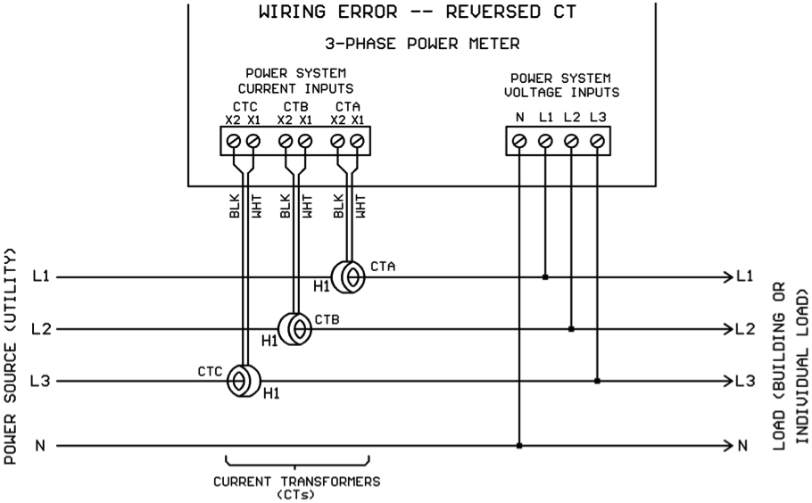
With CTC’s H1 facing the wrong direction, the power meter will either read a Phase C power of zero (if meter is not capable of bi-directional power measurement) or it will read a negative power (if meter is capable of bi-directional power measurement). Either way, the total power measurement is going to be incorrect.
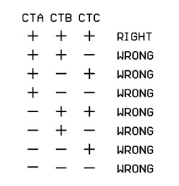
With three CTs, each capable of being installed with plus or minus orientation, there are 8 possible combinations of CT polarities:
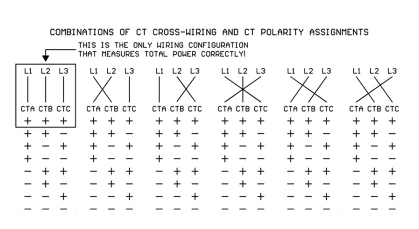
Combining CT Cross-Wiring and CT Polarity Possibilities
Below is a diagram showing the possible CT cross-wiring combinations and the possible CT polarity assignment combinations. Note that out of all the possible combinations, there is exactly one combination that measures total power correctly.
Symptoms of Incorrect Meter Wiring
Incorrect CT-hot wire matching or reversed CT polarities will give lower-than-expected power readings or even negative power readings. Power factor will also read unusually low on the cross-wired phases.
What’s A Poor Installer To Do?
To have a chance of getting it right, you need to pay scrupulous attention to wire assignments. Use different wire colors and/or use stick-on wire tags to unambiguously designate the wire functions at both ends of the wire runs.
Determining Correct Wiring Configuration On An Installed Meter
If you suspect that your meter wiring might be wrong, the best way to determine correct wiring is to physically trace everything out. However, this may be difficult or impossible to do on some installations (for example CTs are sometimes buried inside switchgear which is locked for safety reasons).
If physical wiring inspection isn’t possible then “in theory,” if you are monitoring a constant load, you could rearrange the wiring to try every combination in the table above looking for the highest total KW reading. This isn’t very practical as it would require a tremendous amount of physical wire swapping and it’s unlikely that the load would remain constant during the length of time it would take to do all the wire rearranging.
Some power meters have the ability to sense a reverse-mounted CT (power is reading negative) and electronically flip the CT signal polarity so the black and white CT wires don’t have to be physically swapped on the meter terminals. This is a desirable feature and will increase your chances of a successful power meter installation.
Conclusions
There are many ways to wire a 3-phase power meter wrong and only one way to wire it correctly. Use color coded wire and/or wire tags to clearly identify each wire at the power system connection points and at the meter connection points. Using a power meter with CT polarity auto-correction can eliminate one source of wiring errors.
If the power system connection points will be inaccessible later (locked up inside switchgear for example), try to do your meter testing early when you still have access to the power system connections.
Personal Safety Footnote
Stayin’ Alive, Stayin’ Alive (1977 hit by the Bee Gees)
The connections between a power system and the meter(s) monitoring it involve hazardous voltages. Described below are two ways you could get zapped working with power meter wiring. Please don’t!
News Flash: Power System Voltages are Dangerous
The L1/L2/L3 input terminals on a power meter will have voltages from 120V to 600V attached to them. Never put your fingers inside a power meter unless these high voltages have been de-energized external to the power meter. This seems like common sense, but we had to say it. There, you’ve been warned.
A Tale of Two CTs (or rather two CT Styles)
Current Transformers (CTs) come in two styles:
- “Conventional” or “traditional” CTs have a current output on the secondary wires. The most common output range is 0-5 amps, but there are also some 0-1 amp CTs out there.
- “Safe” CTs have a voltage output on the secondary wires. The most common output range is 0-0.333V, but there are also some 0-1V and 0-2V Safe-CTs out there.
Now this is not obvious, but current-output CTs always need a load attached to the ends of the secondary wires any time the primary conductor (the conductor going through the hole in the CT) has current flowing through it. If you open-circuit the secondary wires of a current-output CT with current flowing through the primary conductor, very high voltages (thousands of volts) can be produced across the open secondary wires! Never disconnect the secondary wires from a current-output CT with current flowing in the primary wire!
Safe-CTs, on the other hand, can safely have their secondary wires open-circuited while current is flowing in the primary conductor. The output voltage will not rise when a Safe-CT is open-circuited on the secondary. There had to be a reason they’re called Safe-CTs, right? So it’s perfectly OK to grab the screwdriver and move Safe-CT secondary wires around on the meter terminal block.
One Final Note On the Two Different CT Styles
This note isn’t so much about personal safety as it is about not burning up your power meter by mis-application of CT styles. Most power meters are designed to accept either 0-5A current-output CTs or 0.333V Safe-CTs, but not both. Here are the consequences of attaching the wrong style CTs to the meter:
- Attaching Safe-CTs to a meter with 0-5 amp CT inputs will not hurt anything, but the amps readings on the power meter will be completely inaccurate.
- Attaching 0-5A CTs to a meter with Safe-CT inputs will destroy the CT input circuits in the meter! So please, don’t attach 0-5 amp CTs to your Safe-CT meter inputs.