Kele Blog

Back to Basics: Process Tips for Periodic Inspection of Fire and Smoke Dampers

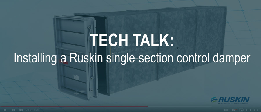
  1. Verify that there is full unobstructed access to the damper
  2. Test the damper with normal HVAC airflow and verify that it opens following either Option 1 or Option 2. There should be no interference due to rust, damaged frame or blades, or other moving parts.

OPTION 1: Dampers with position indication wired to indication lights or control panels:

  • Switches can be wired to local or remote-control panels or building automation systems (BAS) to indicate that the damper is in the fully-open position, fully-closed position, or neither.
  • Use the signal from the damper’s position indication device to confirm that the damper is in the fully-open position.
  • Remove electrical power or air pressure from the actuator to allow the actuator’s spring return feature to close the damper.
  • Use the signal from the damper’s position indication device to confirm that the damper reaches its fully- closed position.
  • Re-apply electrical power to re-open the damper.
  • Use the signal from the damper’s position indication device to confirm the damper reaches its fully-open position.

OPTION 2: Dampers without position indication:

  • Visually confirm that the damper is fully-open position.
  • Ensure that all obstructions, including hands, are out of the path of the damper blades.
  • Remove electrical power or air pressure from the actuator to allow the actuator’s spring return feature to close the damper.
  • Visually confirm that the damper closes completely.
  • Re-apply electrical power to re-open the damper.
  • Visually confirm that the damper is in the fully open position.
  1. If the damper is not operable, it must be repaired as soon as possible. If the actuator has failed, replace it with a UL-approved actuator. After these repairs, the damper should be tested again.
  1. If there is a latch, verify that it is operable.
  1. Perform any other damper manufacture-recommended maintenance such as lubrication.
  1. Following the test and any repairs, document the location of the damper, the date, the inspector, and deficiencies or repairs. Keep the record for the life of the damper and have it available as you may need to show it to an inspector.

If you need assistance, contact Kele’s technical service team. We’re here to help.

Guidance for Inspecting and Maintaining Fire and Smoke Actuators and Dampers

Contributed by Ruskin

A fire damper can be defined as “a device installed in ducts and air transfer opening of an air distribution or smoke control system designed to close automatically upon detection of heat. It also serves to interrupt migratory airflow, resist the passage of flame, and maintain the integrity of the fire rated separation.” Its primary function is to prevent the passage of flame from one side of a fire-rated separation to the other.

The significant protection capabilities of fire dampers to life and property are now widely recognized by Facility Managers throughout the United States. More and more Authorities Having Jurisdiction (AHJ’s) and building owners are requiring fire dampers to be operational tested and maintained on a regular basis.

AHJ’s are requiring operational tests to determine if the damper will function when needed in order to resist the spread of fire. Operational testing normally involves removing or melting the fusible link and letting the damper close. Once the damper has proven to close, it is reopened, and the fuse link replaced. All the dampers installed in a building must be tested prior to occupancy and again 1 year later under normal operating conditions. Reference NFPA 80 and NFPA 105 for more information.

Applicable Standards

NFPA 80 is the National Fire Protection Association standard that regulates the installation and maintenance of assemblies and devices used to protect openings in walls, floors and ceilings against the spread of fire and smoke within, into, or out of buildings.

NFPA 105 is the standard which prescribes the minimum requirements for smoke door assemblies and smoke dampers that are used as a means to restrict the flow of smoke though openings to provide safety to life and protection of property

Fire Dampers must meet the UL555 Test Standard. UL (Underwriters Laboratories) states that the requirements of UL555 cover fire dampers that are intended for use where air ducts penetrate or terminate at openings in walls or partitions; in air transfer openings in partitions; and where air ducts extend through floors as specified in the standard for installation of air-conditioning and ventilating systems, NFPA 90A.

Testing and Maintenance

AMCA presents a valuable guide for commissioning and periodic performance testing of fire, smoke and other life safety related dampers. This guide provides recommendations for the proper commissioning of fire and life safety related dampers and details the appropriate intervals and methods for performing periodic performance testing of these dampers. This guide can be downloaded for free from AMCA’s website below.

AMCA Guide for Commissioning and Periodic Performance Testing of Fire, Smoke and Other Life Safety Related Dampers (PDF)

To the facility manager operational tests and regular maintenance can present a couple of challenges:

  1. Most fire dampers are installed in areas of the building that are not easily accessible. Fire dampers are installed in penetrations of fire rated walls and floors as required by the building code and access to the damper itself is normally through an improperly sized access door.
  2. Fire dampers can be extremely difficult to test and reset due to their design (all manufacturers utilize the same basic curtain type design). There are two main types of fire dampers: dynamic fire dampers and static fire dampers. Dynamic fire dampers have been UL tested and proven to close against system air pressure and velocity. Static fire dampers, on the other hand, are UL tested but have not been proven to close against system air pressure and velocity. The main difference between the two designs is dynamic dampers (in most cases) utilize springs to pull the curtain closed against the air pressure and velocity while static dampers rely solely upon gravity to pull the curtain closed (static dampers designed for floor installation utilize closure springs). The spring shape and size determine the air pressure and velocity against which the dynamic fire damper closes.

Dynamic fire dampers are becoming more popular with designers as dynamic dampers may be used in either a static system (fans off) or dynamic system (fans on) while static dampers can only be used with static systems.

Limited access and closure springs do not make dynamic fire dampers testing and maintenance friendly despite being life and property friendly as they are guaranteed to close if properly applied and installed.

A solution to the operational acceptance testing problems is to know the testing requirements beforehand. Coordinate with the AHJ and determine what they will accept for testing procedures.

Since dynamic dampers are proven to close, the solution may be a simple installation inspection to make sure the dampers are installed properly with no obstructions.

A solution to the maintenance testing is not so simple. Maintenance should be performed per NFPA80 and NFPA 105 requirements: Each damper shall be tested and inspected after the damper is installed, then one year after installation. The maintenance testing and inspection frequency shall then be every 4 years, except in hospitals, where the frequency shall be every 6 years.

More often than not, the building will be occupied and access to the damper remains a problem; however the use of a motorized fire damper that can be operated from a remote, easily accessible location and can be equipped with position indication for operation verification. A motorized fire damper can be more easily maintained compared to a standard dynamic fire damper and contributes to maintenance and insurance savings. All motorized fire dampers are dynamic rated and may be utilized in place of any static or dynamic curtain blade fire damper.

Dynamic, multiple blade fire dampers provide another solution to the access and maintenance issues posed by the dynamic curtain blade dampers. Multiple blade fire dampers are easy to both test and reset since the blades can be operated and held open via a hand lever or a pair of pliers while the fuse link is replaced. An additional solution for round ducts is the use of a true round fire damper. Round fire damper allows the fusible link to be replaced easily then the damper can be adjusted to its full-open position.

Monitor Your Data Center’s Humidity to Prevent Downtime

Humidity is a frequent topic of conversation this time of year in Kele’s neck of the woods. While the more technically informed meticulously monitor and delineate between relative humidity and dew point for a true gauge of the moisture (i.e., sweat) factor, the end result is certain. August humidity in the Mid-South can be oppressive, drenching, and push many to surrender to a little “downtime.” The same can happen in your data center any time of year, but downtime? Not an option.

Earlier this year, we wrote about strategies to keep your data center cool.  Maintaining humidity in the recommended range is equally important. The American Society of Heating, Refrigerating and Air-Conditioning Engineers 2016 guidelines indicate a range of 20% to 80% relative humidity with a recommendation of around 50%.

Too much humidity in your data increases the risk of condensation. Moisture on your data center equipment can lead to damage, corrosion, and possibly equipment failure.

Generally speaking, relative humidity represents the amount of water vapor the air is holding as a percentage of what it would be holding if it were wet. (50% relative humidity means the air is holding 50% of water vapor it can hold at the current temperature.) Increasing the temperature increases the amount of vapor the air can hold before condensation begins. However, as we discussed, too much heat in a data center is also problematic.

A phrase not in the Mid-South vernacular— “too little humidity”—can also cause potentially catastrophic issues in a data center. If the air becomes too dry, the risk of an electrostatic discharge (ESD) increases. An ESD can generate enough heat to damage small electronic parts, and the high voltage for the discharge can damage other delicate components.

Monitoring humidity is critical. Ensuring the ambient air is flowing how and when it should to maintain the appropriate relative humidity is the key. Refer to our diagram for where duct humidity sensors are typically located in an air handling unit. Kele has a broad selection of duct humidity sensors from several reputable supplier partners. Our project and technical services teams will help you think through your entire air handler system on the front end and select the right components, including humidity sensors.

Give us a call or send an email—from the cool comfort of your favorite indoor spot this August, of course. The Kele team is here to help.

Siemens Humidity Sensors – Highly stable measurement under all conditions

When it comes to energy-optimized control concepts, Siemens humidity sensors guarantee fault-free operation for years, even in critical applications. Thanks to the capacitive measurement element, they feature excellent long-term stability with high accuracy, freedom from maintenance and high precision. Microprocessor technology and a sophisticated algorithm for temperature compensation ensure high accuracy not only in the comfort range but also over the entire measurement range.

Choose from a wide range of sensors that covers the full range of humidity measuring applications in HVAC systems. View the dta table below for more detail on each sensor option.

Kele Delivers for a Project on the Edge of the Galaxy

Very recently in a theme park in a state not too far away …

It is a series of products from Kele: Flow meters, sensors, and temperature transmitters for compressed air systems that our teams have installed. Kele ally Advanced Environmental Systems & Core Controls, Inc. has won a new victory in providing for a mouse-loving park in Florida with the help of Kele, as a custodian of the various parts needed to bring joy across the Galaxy’s edge.


The Advanced Environmental Systems and Solutions battle plan:

If you need to form a BAS alliance, need product reinforcements, or advice from a master, Kele will always be with you. With 50 expert sales associates and a massive in-house inventory of 1.8 million parts from 300+ suppliers, Kele can fill your next galactic order or entire BOM.

If you would like to contact us today, please email us, call us at 877.826.9045, or use the Force.

TECH TALK: Installing a Ruskin single-section control damper

As part of their how-to video series, Ruskin shows you the steps to installing a single-section control damper. Steps are shown on how to remove the extended shaft and measure from the bottom of the damper to the center of the appropriate axle. You’ll also learn how to measure along the section of duct to calculate where the extended shaft will be located. Once holes are cut, the method of correctly positioning the damper into the shaft, securing, and re-placement of the extended shaft back onto the damper axle is shown. When this is finished, the install is completed by caulking the damper into the sleeve.

This is a great guide whether you’re a beginner or a seasoned veteran looking for a refresher. Don’t forget to call or email Kele for all your control damper and actuator needs.

Shop Ruskin dampers here.

Kele CEO Richard Campbell Discusses the Temperature Control Systems Acquisition on ControlTalk Now

On July 8, Kele announced its acquisition of Dallas-based Temperature Control Systems. The company’s third acquisition in less than two years, Kele will be able to serve customers in the south-central U.S. even faster. Kele CEO Richard Campbell recently spoke with ControlTrends on the ControlTalk Now video podcast about why the move makes sense for both companies. He was joined by Temperature Control Systems President Scott Cross. Campbell also provides Kele’s enlightening backstory and thoughts about what Kele is focused on next.

Click here to view the entire podcast.

Kele Completes Acquisition of Temperature Control Systems, Inc.

Acquisition is Kele’s third since 2017 and strengthens service to the south-central U.S.

MEMPHIS, Tenn. and DALLAS – Kele, Inc. today announced the acquisition of Temperature Control Systems, Inc. The acquisition expands Kele’s footprint and enhances its ability to serve customers in the south-central United States. Temperature Control Systems, which is headquartered in Dallas with six locations across Texas and Oklahoma, will increase its offering with a broader product line, value-added services, and faster delivery options.

Kele President and CEO Richard Campbell said customers from both companies will realize benefits from the acquisition.

“Two established, value-added distributors joined forces today, and we are excited about the future” said Campbell. “This move demonstrates Kele’s ongoing commitment to transform both how and where we serve customers with industry-leading products and custom solutions.”

Temperature Control Systems is a full-line stocking distributor of commercial HVAC controls and building automation systems. The company serves customers in Texas, Oklahoma, Arkansas, and Louisiana. This marks Kele’s third acquisition in less than two years. In October 2017, Kele initiated its strategic growth plan by acquiring Control Consultants, Inc. (CCI) of Boston and continued last June with the purchase of MIControls, which has locations in Seattle and Portland, Ore.

“For the past two years, Kele has worked to get products closer to our customers for even faster delivery” said Campbell. “We have already seen success in the Northeast and Northwest from the CCI and MIControls branches. Temperature Controls Systems will strengthen our ability to serve customers in the south-central region, and specifically across Texas, Oklahoma, Arkansas, and Louisiana.”

The new entity will operate as a separate brand. Campbell will serve as president and CEO of the combined company. Scott Cross will remain as president of Temperature Controls Systems and lead its locations.

“Temperature Control Systems is excited to join Kele,” said Cross. “Our customers can expect the same value-added service they’ve experienced for more than 40 years. Aligning with Kele will help us meet even more of their needs through additional product lines, services, enhanced order fulfillment, and new digital and eCommerce tools.”

Kele’s acquisition of Temperature Control Systems was effective June 28, 2019. Blank Rome, LLP acted as legal counsel to Kele. Silvermark Partners, LLC acted as financial advisor to Temperature Control Systems, and Wick Phillips, LLP served as its legal counsel.


About Kele, Inc.

Kele, Inc. is a leading distributor of building automation products and controls solutions globally. Kele serves the $50+ billion building automation systems (BAS) market with more than 300 brands and 1.8 million parts in stock, including sensors, transmitters, switches, gauges, valves, actuators, relays, and more. Kele’s products can be integrated into existing buildings or new construction. Value-added services include custom panel assembly, specialized sourcing, and technical support. Strategically headquartered in America’s logistics hub, Memphis, Tenn., and with regional locations in Boston, Seattle, and Portland, Ore., Kele provides building automation and industrial customers with fast and reliable services. Kele is owned by private equity firm Snow Phipps, LLC. To learn more about Kele, visit kele.com.

About Temperature Control Systems, Inc.

Temperature Control Systems is a full-line stocking distributor of commercial/industrial HVAC controls, burner/boiler controls, and building automation systems. Since 1975, it has grown into a multi-branch, nationwide distributor. Temperature Control Systems prides itself in customer satisfaction, focusing on providing products and best-of-class solutions as well as training. For more information, visit temperaturecontrolsystems.com.


Keep Your Data Center Cool with Kele: Part 2

Part 2: Planning for a Computer Room Air Handler

In Part 1 of Keep Your Data Center Cool with Kele, we outlined a variety of strategies to remove heat from a data center. Doing so is critical to successful 24/7 operation, lest electrical components malfunction, servers exceed their maximum temperature, and equipment go offline. The most common solution is a Computer Room Air Conditioner or Air Handler. (These are CRAC and CRAH, respectively. We will use CRAH in this article).

Essentially, a CRAH blows cold air in a set path to remove hot air from the area using a variety of devices keep everything flowing properly. Internal heat exchangers connect to refrigeration systems or water chillers to remove heat. Filters remove dust while fans circulate and distribute the air. A CRAH may also include humidifiers or dehumidifiers to help control static electricity in the air.

While some data center server rooms are positioned on a raised floor with a CRAC underneath, a CRAH is typically located overhead and blows cool air downward. If your data center employs a hot aisle/cold aisle strategy (summarized in Part 1), you have options. The CRAH can be placed to send cool air down directly to the cold aisle or above the hot aisle where it will force hot air up to be cooled through the system.

As your project engineer works through the CRAH system plan, he/she must also consider the list of components essential to controlling the system and monitoring the surrounding environment. These are as important as the system itself. See below for a breakout of typical CRAH system components. Each is listed with a brief description of its purpose.

Breakout of a Typical Air Handling Unit and its Components

CRAH Components 

  • Control Dampers – regulate the amount of air in CRAH.
  • Direct Coupled Spring Return Actuators – open and close dampers.
  • Outside Airflow Measuring System – measures the amount of airflow in the CRAH.
  • Differential Pressure Switch – senses difference in pressure between two points.
  • Duct Temperature Sensor – measures the temperature at the sensor location.
  • Chill Water/Hot Water Valves (zone, ball globe valves) – regulate water flow through a coil.
  • Current Switch – shows on/off Status of fans, pumps, and motors.
  • Low-Limit (freezestat) Detector – protects equipment on low temperatures.
  • Duct High-Temperature Limit (firestat) Detector – protects equipment on high temperatures.
  • Airflow Measuring Station – measures the amount of airflow in the CRAH.
  • Differential Pressure Transmitters – sense the difference in pressure between two points and produces an output signal.
  • Duct Humidity Sensor – measures relative humidity at the sensor location
  • Duct Smoke Detectors & Remote Accessories – shut down the unit when the detector senses smoke.
  • Air Velocity Measurement – used to control air velocity to balance out pressure fluctuations
  • Differential Pressure Gauge – visual indication of the difference between two pressure points. (e.g., measures pressure on both sides of an air filter)

Kele can equip you with every product you need to monitor and control temperature, humidity, and pressure, and to manage airflow. We can also provide parts to monitor compressor and chiller run time to track energy consumption. Kele’s project services team will help you think through your entire project BOM on the front end and select the right components for your system. If you have questions about anything you see above, our technical services team can provide answers

Over the past few months, we covered the rapid growth and permanence of data centers—including the need for speed when building them. We summarized a variety of cooling strategies to remove heat and keep equipment and servers online. And above we outlined the inner workings and essential components to the most common cooling strategy.

Hopefully, you are better equipped with the information you need for cooling your data center. Kele is here with the service and products you need to make it happen. Contact us today. And stay cool.

ONEBOX Becomes Part of the RET Legacy with a New Name and New Sizes

Did you know that the legendary RET Series just got a new family member?

The ONEBOX NEMA 4 enclosure has been renamed the RET4 after our popular NEMA 1 legacy series of enclosures. The RET series has been a top choice among Kele customers for more than three decades. It seemed only appropriate that ONEBOX, also a Kele enclosure series, officially add to the RET legacy with a NEMA 4 option.

With a new name comes exciting new sizes! RET4 will now be available in seven unique sizes (14 models in total), all with optional perforated subpanels. The new sizes are as follows:

  • RET4-121806LG – 1.8H x 17.7W x 5.9D (in)
  • RET4-202010LG – 19.7H x 19.7W x 9.8D (in)
  • RET4-393210LG – 39.4H x 31.5W x 9.8D (in)
  • RET4-483210LG – 47.2H x 31.5W x 9.8D (in)

RET4 will retain the same reliable design of NEMA 4 enclosures, offering protection from windblown dust, rain, ice, and hose-directed water. RET4 is perfect for all indoor and/or outdoor applications and provides a safe space to mount electrical instruments, controllers, and power supplies with interconnecting wiring.

Shop the RET4 Series here.

Explore the RET4 series today for your next enclosure need!