Contributed by Henry Smith, Design Engineer – Functional Devices, Inc.
A Functional Devices customer recently sent a technical email asking if a RIB® relay could be used in place of a 4-way switch. I informed him that any of our DPDT relays could be wired to act as a 4-way switch, and any of our SPDT relays could be wired to act as a 3-way switch.
Most of us are familiar with 3-way switch applications as they are common in homes. They are typically used for controlling lighting in a room with two entrances so that the light may be turned ON or OFF while entering or exiting either way. A 4-way switch application serves the same purpose but would incorporate three or more switches, all toggling the same light. The first and last switches in the line would be 3-way switches, and as many additional switches as needed in between would be 4-way switches.
To use a DPDT relay as a 4-way switch, the Normally Open (N/O) contact of pole one would be wired to the Normally Closed (N/C) contact of pole two. The N/C contact of pole one would wire to the N/O contact of pole two, like the RIB24P contacts in the Figure below. The following diagrams and explanations will hopefully make this application clearer.
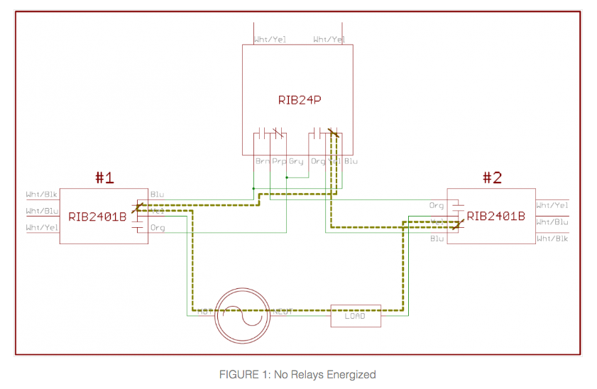
In the above diagram, none of the relay coils would be energized, and all their contacts would be in their normal state. This provides a continuous path through the Normally Closed contacts, and the Load is powered. Let’s say that Relay #2 has its coil energized. At that point, the relay contacts would change state. There will now be continuity between the Org and Yel wires, instead of the Blu and Yel wires. This is shown in the next diagram.
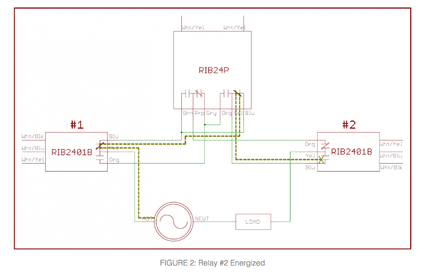
With Relay #2 energized as above, the path from the source to the Load has been broken and the Load would turn OFF. If Relay #1 would have been energized instead of Relay #2, the path for electrical flow would be as shown in the next diagram.
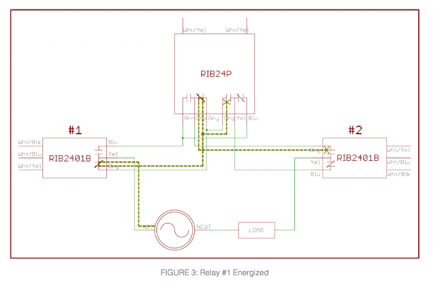
Since the contacts on Relay #1 changed state, there is a new path through its N/O contact to the RIB24P. However, there is no longer a complete path from the source to the Load, and it will not be powered. If RIB24P had been energized instead of Relay #1 or #2, the Load would also be OFF. This can be seen in the Figure below.
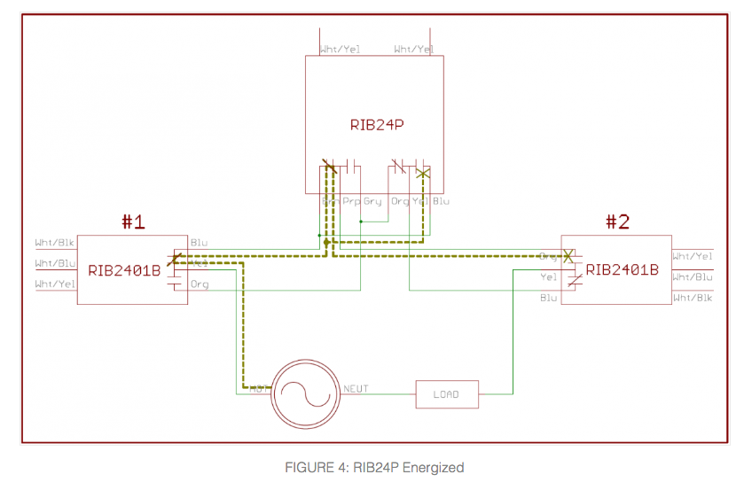
Again, the path from Source to Load has been interrupted, and the Load would be OFF. If either Relay #1 or #2 were to be energized at this point, the Load would toggle ON. The final Figure shows the path if RIB24P and Relay #2 are energized at the same time.
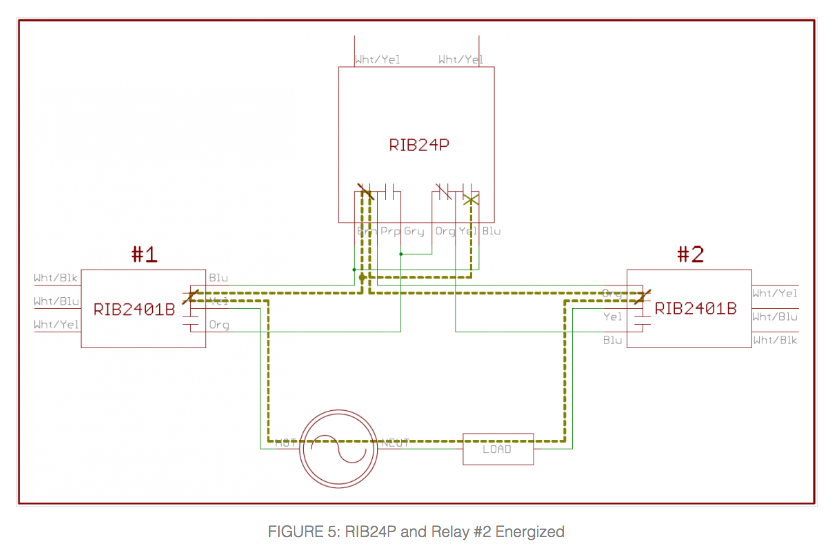
When Relay #2 is energized, the N/O contact closes between the Org and Yel wires. The path from the Source to the Load is complete again, and the Load would turn ON.
Any number of DPDT relays can be cascaded together to add more switches to the setup above. There will always be two wires in (from the LINE side) and two wires out (to the LOAD side). Just make sure they are rated to handle the Load they are to control.


