The Tech Support crew here at Kele frequently gets quizzed by customers who have a voltage-output signal source which must drive multiple voltage-input loads. Requests for “voltage signal replicators” come in frequently. Sometimes extra hardware is needed, but sometimes it isn’t! So we thought it might be a good idea to write an article addressing this topic. Here we go…
*** A note about the terms “resistance” and “impedance”
When looking at data sheets for HVAC control modules, you may see the terms “resistance” or “impedance” used in describing signal input/output loading characteristics. Strictly speaking, “resistance” and “impedance” are different entities (impedance = resistance + reactance) but for a slow-moving control signal which is what we usually have in the HVAC world, the two terms can be used interchangeably. So don’t worry about whether the data sheet says “resistance” or “impedance” we’ll take them to be the same thing. In this article we’ll use the term “impedance” because it’s one letter shorter than “resistance” and we’ll save keystrokes!
Impedance is measured in units called “ohms.” If you don’t know what ohms are, don’t worry. All you have to do is poke the numbers into some simple calculations later on. You may see a suffix “k” or “K” appended after the ohms value on a data sheet. This is important to note! The “k” or “K” means “times 1000” so an impedance of “100K” means 100,000 ohms and that’s the number you would put into your calculations.
On with the show…
The first thing we must do is answer a few questions about the signal source and loads:
- Do the Signal Commons on the different loads have to be isolated from each other?
- Does the Signal Common on the voltage source have to be isolated from all loads?
- What is the “minimum load impedance” the signal source can drive (data sheet item)? (Alternately, this could be specified as “maximum output current”).
- What is the “input impedance” of each of the voltage-input loads (data sheet item)?
The first two questions are sometimes difficult to answer, and are application-dependent. If you cannot find concrete answers, you can always assume that every device must have isolated signals. This approach will always work, but it will also cost more money as signal isolator hardware is required.
With regards to question #3, the signal source data sheet may specify a “maximum output current” value instead of “minimum load impedance.” The “maximum output current” will be expressed in units of mA (milliamps). No worries, we can calculate what we need by this equation:
Minimum load impedance = Largest output voltage required/maximum output current
As an example, suppose the signal range of interest is 0-10V and the maximum output current available from the signal source is 2 mA (0.002 amps):
Minimum load impedance = 10V / 0.002 amps = 5000 ohms
Calculating “equivalent load impedance”
When connecting voltage loads in parallel, you’ll need to calculate the “equivalent load impedance” of all the loads connected together. There are a couple of ways to do this:
If all load impedances are the same—
Equivalent load impedance = impedance of one load / number of loads
If the load impedances are different –
Equivalent load impedance = 1 / (1/Load1 impedance + 1/Load2 impedance + …)
The second calculation is most easily done using the 1/X key on your calculator. Just do a 1/X calculation for each load impedance and add the terms together. Then do a final 1/X calculation on the first result. Here’s an example—
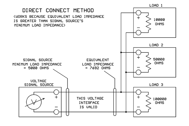
Load 1 = 10,000 ohms (10K)
Load 2 = 50,000 ohms (50K)
Load 3 = 100,000 ohms (100K)
Equivalent load impedance = 1 / (1/10000 + 1/50000 + 1/100000) = 7,692 ohms
The two rules that must be satisfied
There are basically two rules that must be satisfied when driving multiple loads from a voltage source:
- If electrical isolation is required, you must add a hardware signal isolator module to each device to be isolated.
- At each voltage output-to-input interface, the equivalent load impedance of the loads connected together must be higher than the minimum load impedance of the signal source
Case 1: It’s OK for all devices to have their Signal Commons tied together
This case can be done using direct wiring (NO extra hardware) if the equivalent load impedance (calculated above) is greater than the signal source’s minimum load impedance:
That’s great UNLESS… your equivalent load impedance is smaller than the voltage source’s minimum load impedance. Then what are you going to do?
When the equivalent load impedance is too small for the signal source to drive directly, you will need to insert a “signal booster” device of some sort between the original signal source and the loads. The signal booster doesn’t need to boost the voltage (you typically want the same voltage out that’s coming in). It needs to boost the available current so there is enough to drive all the loads connected together.
The Kele UAT is a good device to use as a signal booster in this application. A look at the data sheet shows that its voltage output can drive up to 20 mA of current. Let’s assume that the signal range of interest is 0-10V so the maximum voltage we ever need to output is 10V. Then the minimum load resistance supported by the UAT would be:
UAT minimum load resistance = 10V / 0.020 amps = 500 ohms.
This is plenty of drive power for most parallel-connected voltage loads.
Now when we insert a signal booster device, we must insure that the input impedance of the booster itself is not too low for the original signal source. We see that the UAT input impedance on the 0-10.9V range is 156K ohms (156,000 ohms). If your UAT data sheet shows 156 ohms input impedance, don’t panic! It’s really 156K, some data sheets have a typo. Our apologies. So the UAT input impedance of 156K is far higher than the signal source’s minimum load impedance of 5K, and it’s all good:
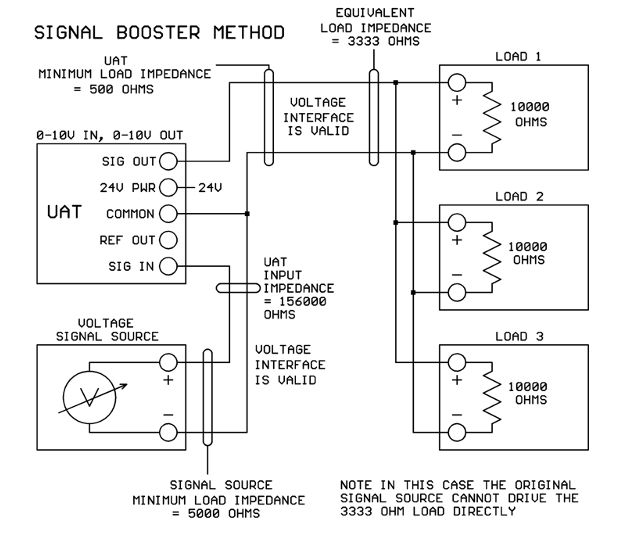
Now you should understand that the UAT does not provide signal isolation as it has one Common terminal for both signal input and output. If you require isolation between devices, read on…
Case 2: Load Signal Commons can be tied together, but voltage source needs isolation
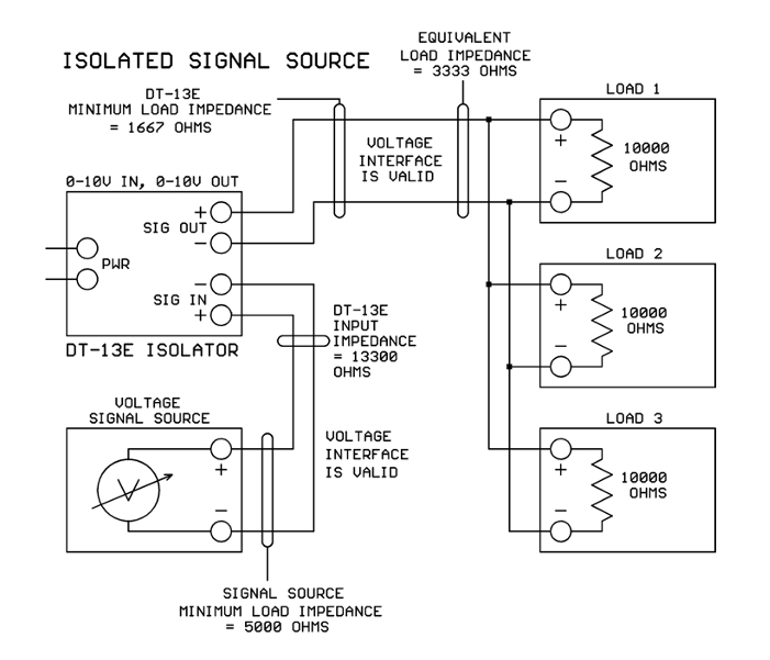
In this case you will need a signal isolator device such as the Kele DT-13E. On the DT-13E, the input signal terminals are completely isolated from the signal output terminals and both of those terminal sets are completely isolated from the power terminals.
We look at the DT-13E data sheet and see that the input impedance on the 10V input range is 13.3K. This is higher than the signal source’s minimum load impedance of 5K, so there is no problem driving the DT-13E input from the original signal source.
Looking at the DT-13E voltage output, we see that the maximum current available is 6 mA. For a 0-10V signal, the max voltage we need to drive out is 10V so the DT-13E’s minimum load impedance will be:
DT-13E minimum load impedance = 10V / 0.006 amps = 1667 ohms.
If we have the same three 10K loads paralleled as in the previous example (3333 ohms equivalent load) then the DT-13E has enough drive and this setup should work just fine:
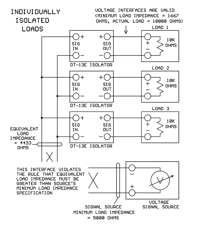
Case 3: Load Signal Commons must be isolated from each other
In this situation, each load will need its own signal isolator module like the DT-13E. The most obvious setup to use is shown in the next figure. When we do the load calculations, however, we find that three DT-13E inputs in parallel will present an equivalent load impedance of 13.3K / 3 = 4433 ohms. Oops, that is lower than the minimum load impedance of 5000 ohms specified for the signal source:
How do we fix this problem? Here are some possibilities:
- Use a different signal source with more drive capability.
- Use different signal isolators with higher input impedance.
- Try rearranging the wiring using the devices that we have.
Let’s see what we can do with option #3. Realizing that inputs and outputs are isolated on the DT-13E modules, it’s perfectly legal to take one of the DT-13E inputs and drive it from another DT-13E’s output. Let’s check the math to see if this would work.
With only two DT-13E inputs paralleled on the signal source, the equivalent output impedance would be 13.3K / 2 = 6650 ohms. This is higher than the signal source’s minimum load requirement of 5000 ohms, so that works.
With the new arrangement, one DT-13E output will drive a parallel combination of the original 10K load and one DT-13E input (13.3K). The equivalent load impedance will be:
Equivalent load impedance = 1 / (1/10000 + 1/13300) = 5708 ohms.
This is higher than the DT-13E output’s minimum load impedance of 1667 ohms so that works too! And this is the final configuration:

Conclusions
By following the two interface rules discussed above, multiple voltage-input loads may be successfully driven by a common voltage-output signal source. The math is simple algebra and can be done on any calculator. Happy interfacing!


this was helpful, which scenario would work best with sending a 0-10Vdc signal from a BAS controller to multiple VFDs in a fan array so they can share the same speed reference signal and ramp up and down together?
VFD installation guides frequently call for an isolated 0-10V signal from the controller’s analog output. Since VFDs may be located quite some distance from the controller this is a good idea to prevent “ground loop” issues.
Although we would like to think that “Ground” is the same everywhere in a building, this isn’t true. “Ground” points at different physical locations can be at different voltage potentials, so when the analog signal’s “Common” wire is connected to Ground at both ends, noise currents start to flow through the Common wire, interfering with the 0-10V analog signal.
Inserting a signal isolator between the controller’s analog output and the VFD’s input breaks the direct physical connection on the Common wire and eliminates the interfering noise currents. So the VFD manufacturer has a valid reason for asking for an isolated 0-10V signal.
Now for an array of VFDs all sitting in the same physical location, “Ground” is going to be very nearly the same potential at every VFD signal input. In this case I would try simply connecting all the VFD inputs in parallel and feeding the entire array from one DT-13 isolator connected to the controller analog output. If the combined parallel input impedance of all the VFDs together is too low for a single DT-13 to drive, separate the VFD inputs into two or more banks and drive each bank with its own DT-13 isolator.
I doubt that you would need to provide a separate DT-13 signal isolator for every VFD in an array if the VFDs are physically sitting close to each other. However, if you want to be ultra-conservative you can certainly put an isolator on each VFD input.
Dave Irby, PE
Panel Engineering
Kele Inc.
Hello, great article but the images showing the final configurations are missing. Any chance they can be added back to this post? I am picturing the configuration in my head but I would love to see if what I am thinking is the same.
Hello Matt,
Thank you for letting us know about the missing images. That has been corrected. Please feel free to post here or contact our tech group if you should have any questions.
Kele Inc