Kele designed the Universal Flow Transmitter (UFT) for use with Badger/Data Industrial flow sensors, but in reality the UFT can be used with many other makes and models of flow sensors if their signal outputs are compatible with the UFT signal input.
Kele frequently gets asked the question “will this Model XYZ flow sensor work with the UFT?” So we decided that it might be a good idea to write an article addressing this topic and at the same time provide other application information beyond that shown on the UFT data sheet.
UFT Power
The UFT requires 24VDC +/- 10% at 80 mA maximum for operation. Note that the UFT cannot be powered with 24VAC.
UFT Flow Sensor Input Circuit
The UFT will accept pulses from the following types of flow sensors:
- Sensor output that is open-circuit in the “high” state and conducts to common in the “low” state. Most Badger/Data Industrial flow sensors operate this way. For this type of sensor output, install the “PWR XDCR” jumper located near the PWR LED across both pins of the header. When the sensor contact is open, 8V will appear across it. When the sensor contact is closed, 8 mA of current will flow through it.
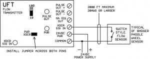
Figure 1: Switch Style Flow Sensor - Powered sensor output that drives to a “high” value of +5 to +24VDC and drives to a “low” value of 0 to +2VDC. For this type of sensor install the PWR XDCR jumper on just one pin of the 2-pin header.
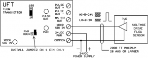
Figure 2: Voltage Drive Flow Sensor
Up to 2000 feet of sensor cable 20AWG or larger can be used with the UFT, but to reduce noise pickup, please use the shortest length of sensor cable actually needed for the application.
The flow sensor must put out no pulses (0 Hertz signal) with no flow.
To be compatible with the UFT Span adjustment range, the flow sensor must put out pulses between 15 Hertz and 150 Hertz at full flow velocity (max GPM).
There is an XCDR SIG IN LED that indicates the state of the input signal from the flow sensor. When the input is “high” the LED is on, when the input is “low” the LED is off. When the pulse rate is fast, the LED may appear to stay on continuously even though it is actually going on and off very rapidly. If the sensor is working properly, you should always be able to see the LED flashing when the flow is first starting up or ramping back down to zero. At no flow, the XDCR SIG IN LED may be either on or off depending on the resting state of the flow sensor output.
The UFT can be factory modified to handle higher input frequencies (up to 1000 Hertz) at max flow velocity. It cannot be modified to handle any frequency lower than 15 Hertz at max flow velocity.
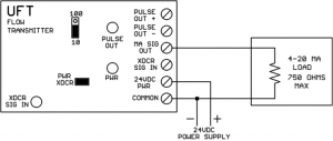
4-20 mA Output Circuit
The 4-20 mA output represents the instantaneous (averaged over about 5 seconds) flow rate. The UFT powers (sources) the 4-20 mA internally, an external power supply should not be inserted in the 4-20 mA loop. The output will be 4 mA at 0 GPM (no flow). The output will be 20 mA at whatever maximum flow GPM the UFT is calibrated for.
The 4-20 mA output is designed to drive a maximum load impedance of 750 ohms. If the mA output is open-circuited, approximately 20V will appear between MA SIG OUT and COMMON.
The 4-20 mA output normally comes from Kele pre-calibrated for the sensor model and maximum flow rate specified on the customer order. When Kele calibrates the UFT, a label is attached to the top of the board specifying the calibration parameters.
Field Calibration (Not Recommended)
The UFT can be field calibrated if a steady maximum flow rate can be maintained (see following procedure).
Caution: once the SPAN pot is turned in the field, it will be impossible to fall back to the factory calibration setting that was done at Kele.
- Stop flow completely (or disconnect sensor wire) and trim the ZERO pot for 4 mA output.
- Establish steady max flow rate and trim SPAN pot for 20 mA output.
The 4-20 mA output changes slowly when trimming the ZERO and SPAN pots, you must be patient and wait for the output to stop changing with each pot adjustment.
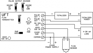
Pulse Output Circuit
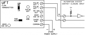
The UFT pulse output circuit can be used to drive a mechanical/electronic totalizer or an automation system binary input point for gallon totalization in software.
The UFT pulse output is optically isolated from the remaining UFT electronics. The pulse output does not drive any voltage of its own, the voltage must be provided by the load. The pulse output connections are polarity sensitive.
In the “high” state the pulse output is open-circuit. In the “low” state the plus and minus terminals are connected together with approximately a 0.7V difference between them. This will be seen by most automation system binary inputs as a contact closure. The UFT pulse output can operate from 1-40VDC in the “high” (open) state. The UFT pulse output can carry as much as 200 mA in the “low” state
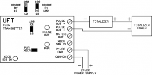
The pulse output is jumper-selectable for divide-by-10 or divide-by-100 operation. For divide-by-10 operation, one complete (high and low) output pulse is generated for each 10 sensor pulses. For divide-by-100 operation, one complete (high and low) output pulse is generated for each 100 sensor pulses. There is no other calibration for the UFT pulse output (no trimpots). There is a PULSE OUT LED which indicates whether the pulse output is open-circuit (LED off) or conducting (LED on). Note that if the pulses stop coming from the flow sensor, the output could stop in either the open-circuit (LED off) or conducting (LED on) state.
Testing the UFT Without a Flow Sensor
- Disconnect the sensor wire (if present) from the XDCR SIGNAL IN screw.
- Install the PWR XDCR jumper on both header posts.
- Move the divide-by-10/100 jumper to the 10 position.
- Connect a jumper wire to the Common screw.
- Tap the other end of the jumper wire on the XDCR SIGNAL IN screw.
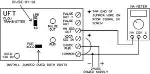
As you tap the wire, you should see the XDCR SIG IN LED go on and off. The PULSE OUT LED should cycle on and off for every few taps of the wire. The mA signal should rise above 4 mA and the faster you tap, the higher the mA should go. If the UFT behaves as described above, it is functioning properly.