Editor’s Note – February 20, 2026: This article has been reviewed for technical accuracy and remains applicable to current HVAC controllers and pulse output applications. Based on customer feedback, we’ve also linked it directly to relevant UPD Series Transducer product pages for easier reference during design.
Some HVAC applications require reading and totalizing pulses from flow meters. This sounds simple enough, just take the pulse output from the flow meter, connect it to a Binary Input (BI) on your controller, and set up the program logic to count pulses coming in on the BI. What could go wrong?
Unfortunately things are not always as simple as they appear. HVAC controllers frequently operate on the “scan” principle where the inputs are not read continuously, but only once per controller scan. Controller scan time could be fast or slow depending on the controller design.
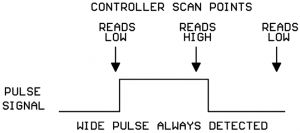
The controller only “sees” a pulse if the input is low on one scan and high on the next scan. This means that:
- A pulse whose duration is longer than the time between controller scans should always be reliably detected:
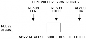
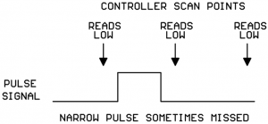
2. A pulse whose duration is less than the time between controller scans will sometimes be detected and will sometimes be missed:
NOTE: some controllers have one or two “high-speed counter inputs” in addition to their regular Binary Inputs. High-speed counter inputs have a much higher scan rate and may be fast enough to detect your flow meter pulses reliably with no additional hardware needed. Always check the controller data sheet to see if your controller has any high-speed inputs you can use for connecting your flow meter.
What can I do if my flow meter pulses are too narrow to be reliably detected by my controller?
Kele sells a Universal Pulse Divider (UPD-2) that can divide the incoming meter pulses by a selectable divisor and output a wider pulse that your controller can reliably detect.
What kind of pulse signals can the UPD-2 accept on its input?
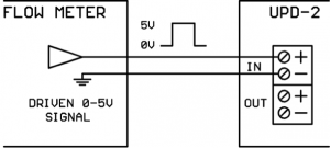
The UPD can accept pulses from a simple contact closure, a transistor switch, or a driven 0-5VDC signal:
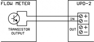
In the Low state, the output of the flow meter must be able to sink approximately 2.3 mA of current. This will be compatible with most flow meters.
What kind of output does the UPD provide?
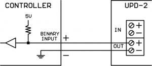
The UPD output is an optically-isolated electronic switch. It is polarity sensitive. In the High state it is open-circuit, in the Low state it closes the circuit. In the Low state, the output can sink up to 6 mA of current. In the High state, it can tolerate up to 30VDC. The UPD output is compatible with most controller Binary Inputs which are typically configured as an internal reference voltage with a pull-up resistor as shown below:
What is the minimum high or low pulse time the UPD will detect on its input?
The UPD will reliably detect any pulse with a high or low time of at least 10 milliseconds. This limit is programmed into the UPD’s microcomputer firmware, the hardware could actually detect shorter pulse durations. But HVAC equipment lives in electrically noisy environments, and we don’t want to start counting noise glitches as flow meter pulses, so we set the minimum valid pulse duration at 10 milliseconds.
How do I set the divisor value on the UPD?
The UPD has an 8-slider DIP switch for setting the divisor. Each slider has a divisor value assigned thus:
- Slider 1 = divide-by-1
- Slider 2 = divide-by-2
- Slider 3 = divide-by-4
- Slider 4 = divide-by-8
- Slider 5 = divide-by-16
- Slider 6 = divide-by-32
- Slider 7 = divide-by-64
- Slider 8 = divide-by-128
The total divisor value is the sum of all the sliders which are turned on. For example, if sliders 2 and 3 are turned on, the total divisor is 2+4 = 6.
** After changing the DIP switch sliders, be sure to cycle the UPD power as the DIP switches are only read by the microcomputer chip at power-up.
How does the division logic work on the UPD?
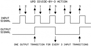
It’s important to understand how the UPD division logic works. The UPD counts all the up-and-down signal transitions on the incoming pulse. For every N up or down transitions on the input signal, the UPD makes 1 transition on the output signal (where N is the total divisor selected).
This is one of those times where a picture is worth a thousand words. Shown below is the division action when the total divisor is set to 3 (sliders 1 and 2 On, all others Off):
How do I know what the duration of the output pulse will be?
That totally depends on the durations of the high and low portions of the original input signal. Let’s say that, on the diagram above, the input signal high portion is 15 msec long and the input signal low portion is 25 msec long. If we add those values to the diagram, it’s easy to calculate the duration of the output signal high and low portions:
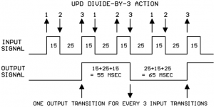
You will note that the durations of the low and high parts of the output are not identical. That’s because we used an odd divisor. If you use an even divisor, the output low and high durations will be identical. If you use an odd divisor, the output low and high durations will be close, but not identical.
You should be able to find some documentation about the flow meter output pulse timing on the flow meter data sheet. Typically the high portion of the pulse is fairly constant and the duration of the spaces between the pulses changes as the media flow rate changes (faster flow = shorter spaces between the pulses).
The flow meter data sheet may specify a nominal pulse width and have a calculation to give the output frequency versus flow rate. This is no problem, if we know the nominal pulse width and the frequency we can calculate the duration of the low part of the signal as follows:
Period of signal = 1/frequency
Duration of low part of signal = period of signal – duration of pulse
For example, say the nominal pulse with is 20 msec and the frequency at max flow rate is 20 Hz.
1/frequency = 1/20 Hz = 0.050 sec = 50 msec period
50 msec – 20 msec pulse width = 30 msec duration for low part of signal
So, the overall approach to using the UPD is this:
- Use flow meter data sheet and anticipated maximum flow rate to figure the shortest duration pulses/spaces that should be coming from the flow meter.
- Use controller data sheet to find the shortest pulse/space that the controller is guaranteed to reliably detect.
- Draw out the flow meter pulse train on paper, including the durations of the pulses and spaces.
- Look at the drawing and start adding together the high and low durations of the meter signal until the sum exceeds the minimum pulse duration required by the controller. If the sum should fall exactly on the minimum spec for the controller, add one more section from the picture as a safety margin.
- Count the number of up-and-down edges for the sections selected in step 4 ignoring the initial rising edge.
- Set the UPD divisor to the number of up-and-down edges counted in step 5.
- In your controller logic, multiply the raw count collected on the Binary Input times the UPD divisor to arrive at the true meter pulse count.
How about an example?
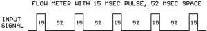
- The flow meter data sheet says the nominal pulse width is 15 msec and the calculated frequency at our max flow rate is 15 Hz.We figure the duration of the low part of the signal as:
1/15 Hz = 0.067 sec = 67 msec period for the signal
67 msec period – 15 msec pulse = 52 msec duration for low part of signal - The controller data sheet says that the minimum pulse width/space that can be reliably detected is 100 msec.
- We draw a picture of our flow meter signal showing the 15 msec and 52 msec times:
- We start adding high and low durations together until we exceed the 100 msec. minimum pulse detect time specified for the controller:
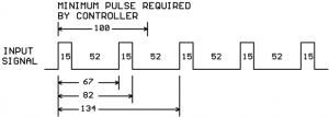
So we see that the output pulse duration will need to be a minimum of two high portions and two low portions of the input signal. - Now count the number of up-and-down edges for the selected sections ignoring the initial rising edge:
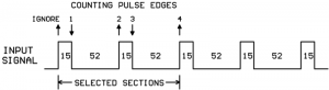
- In step 5 we counted 4 pulse edges (ignoring the initial rising edge) and so we set a divisor of 4 on our UPD by turning on slider #3. And this is the final result of our efforts:
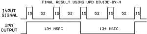
- Keep in mind that every pulse counted by the controller input actually represents four pulses from the flow meter. So to get the true flow meter total counts for your application program, you need to multiply the controller counts x 4.
What happens if you set the Divisor = 1?
You simply get a replica of the original input signal. But remember, the output is electrically isolated from the input so you could use the UPD as a simple pulse signal 1-for-1 isolator.
What else should I know about the UPD-2?
The UPD-2 has an on-board 24VAC isolation transformer for its power supplies so you can get your 24VAC from any convenient source without worries about ground interactions.
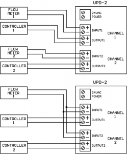
Each UPD-2 contains two completely independent divider sections electrically isolated from each other. One UPD-2 can serve two separate flow meter/controller setups or you can parallel the UPD-2 inputs from one flow meter and get two electrically isolated output pulses:
Conclusions
Flow meter output pulses are sometimes too narrow to be reliably detected on a controller’s binary input if the controller scan time is slow. Inserting a UPD-2 Universal Pulse Divider between the flow meter and controller creates wider pulses that the controller can reliably count. There is a well-defined method for deciding the correct divisor to use on the UPD-2.
The UPD-2 is dual-channel device which can serve two separate flow meter/controller setups or a single flow meter can drive both UPD inputs to create two separate electrically-isolated pulse output signals.


Good article Dave. It easy to understand and also informative. Thank you for sharing this valuable article.
This material needs to be placed in the pdf documentation for the UPD-2.
Thanks for the great suggestion, Jim. We have updated both the UPD-2 and the UPD-4 with a link to this blog in the Tech Tip window.