If you are involved in installing or troubleshooting HVAC systems, sooner or later you will be taking electrical current measurements. This tutorial will discuss the basics of how to take those current measurements.
Current is measured in units of amperes, usually abbreviated to simply “amps.” When working with small currents (less than 1 amp) it may be more convenient to describe current in “milliamps,” typically abbreviated as “mA.”
When you see the term “milliamp” or “mA” this means 1/1000 of an ampere. For example:
4 mA = 4/1000 amps = 0.004 amps
20 mA = 20/1000 amps = 0.020 amps
You might be measuring AC (alternating current) or you might be measuring DC (direct current) depending on the situation. AC current is constantly reversing directions whereas DC current is always flowing in the same direction.
Very likely you will be taking current measurements for one of two reasons:
- Measuring how much current a load draws from its supply (amps or mA, AC or DC).
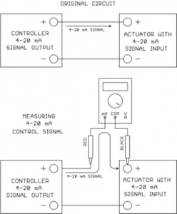
- Measuring a 4-20 mA control signal value (always DC).
Amp-Clamp Ammeter Versus Multimeter
If a lot of your work is done on high-current AC power circuits, an “Amp Clamp” ammeter will be very useful. An amp clamp ammeter has spring-loaded jaws that simply snap around a conductor (no electrical connection required) and the built-in display (analog or digital) reads the amps of current flowing through the conductor:
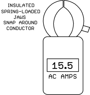
Amp-clamp ammeters are convenient, but they have some limitations:
- Typically an amp-clamp only measures AC amps; it can’t measure DC amps. (There are amp-clamps with a special kind of sensor known as a Hall Effect sensor which can measure DC amps, but these are not typical of most amp-clamps).
- The range covered is usually high (hundreds of amps) so the accuracy on small amp values is poor.
If you are measuring relatively low value AC currents or DC currents, you will likely be using the amps/mA measurement function of a multimeter. A multimeter can measure other quantities besides amps but today we are just concentrating on amp/milliamp current measurements.
Shown below is a typical multimeter face layout. This is an actual meter Kele uses in our internal training classes. It’s a few years old but the functionality of the controls is the same as a modern multimeter. Note that your multimeter controls may be arranged somewhat differently or completely differently. No one likes to do it, but you might want to actually read your multimeter instruction manual if it hasn’t been thrown away/lost by now!
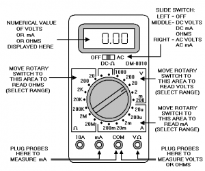
To read current, plug the black meter lead into the COM jack and plug the red meter lead into the mA or 10A jack. Using the mA jack, you can measure currents up to 200 mA on this particular meter. Other model meters may have higher mA ranges available. If you want to measure currents above 200 mA on this meter, you would move the red meter lead to the 10A jack.
Be aware of meter probe properties in the mA/amp mode!
When the meter probes are plugged into COM and mA/amps jacks, the meter’s internal resistance is very low, just a fraction of an ohm. In the current mode, the probe-to-probe path through the meter looks almost like a straight piece of wire!
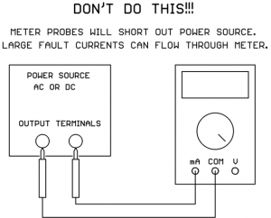
This has important implications. If you put the current meter probes across a power source, you will short out the power source! This makes sense if the probe-to-probe path looks like a straight piece of wire, right?
Many power sources have the capability to produce very large fault currents if their output terminals are shorted directly together. If you do this with your current meter probes, very large currents can flow through the meter!
Because it’s so easy to do this accidentally, most meter manufacturers put an internal fuse in series with the meter’s mA/amp jacks. In that case, hopefully the fuse will blow and protect the meter and the power source. Still, it’s a pain to open up the meter, locate the blown fuse, and replace it.
Some very cheap meters do not have a fuse in series with the mA/amp jacks. If you send large fault currents through one of these cheap meters, the foil on the circuit board will blow apart in lieu of a fuse, rendering the meter a candidate for the trash can. Hopefully your meter does have internal fuses on the mA/amps jacks.
Set the Meter Selector to mA
The meter selector switch has different major areas for choosing whether you want to read voltage, current, resistance (ohms), or possibly other things. You need to move the selector switch to one of the positions in the mA area (lower right area on our example meter). If you are measuring large currents (amps instead of mA) the meter selector may have a separate position for that, or it may still use the mA position since there is a separate jack for amps. Check your meter’s user guide. Our example meter above still uses the selector switch set to mA even though we are using the 10A jack for large currents.
Set Meter Range (Unless You Have an Auto-Ranging Meter)
Our example meter has different current ranges to choose from when using the mA jack based on the maximum current you expect to measure. Choose the smallest range that’s above the highest current you are expecting to measure. If you are not sure what range the current will be, start on the highest range and take a measurement. Then if you can move down to a lower meter range, it will give you better accuracy.
If you accidentally select a lower range than the current you are trying to measure, the meter won’t be damaged unless you put a really large fault current through that blows the fuse. Typically you’ll get some kind of “overrange” indication on the display. This can vary from meter to meter. Sometimes it’s a row of horizontal dashes, sometimes it’s “OL” for overload, or maybe something completely different.
If your meter has an Auto-Ranging function you don’t have to worry about setting the range, the meter will figure it out for you. It usually starts on the most sensitive range and, if it sees an over-range condition, moves to the next higher range etc. until it finds the most sensitive range that does not result in an over-range condition.
Auto-Ranging is very handy. The down side is that it can take the meter longer to display a final stable current reading because it has to trial-and-error each time to find the right range. A fixed-range meter manually set to the correct range will stabilize to a usable reading faster since it doesn’t have to experiment to find the correct range.
Set Meter for AC or DC As Needed
If you set the meter to read DC mA and put the probes in a circuit with AC current, the meter will read essentially zero mA (the readout might jump around the zero reading a bit).
If you set the meter to read AC current and put the probes in a circuit with DC current, the meter display will jump up momentarily then “coast” back down to essentially zero current over time.
So be careful – an incorrect AC/DC meter setting will give completely bogus results!
If you are probing a “mystery circuit” and you’re not sure whether the current between two points is AC or DC, you can try both settings on the meter to see which gives you a non-zero value.
It’s Time To Place the Meter Probes in the Circuit
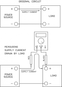
Now this is very important: to take a current measurement, you must disconnect an existing wire in the circuit and connect the meter current probes to take the place of the original connection.
The idea is that you must make the current that would normally flow directly between the two points take a detour and flow through your current meter on the way to its destination:
Remember to keep your fingers on the insulated probe handles, don’t touch the metal probe tips with your fingers just in case the connection contains high voltage. If you have jumper wires with alligator clips, these can be handy for connecting the meter probes into the circuit hands-free.
We’ve shown the current meter connected at the load in the drawings above, but it could just as easily have been connected at the power source/signal source end instead.
In the case of AC current there is no polarity to worry about, the signal will always read positive on the display no matter which way the probes are placed.
In the case of DC current, the red probe should go on the more positive point and the black probe should go on the more negative point. But if you should get it backwards no harm is done, the meter will just display a negative current value, the magnitude of the reading will still be correct and you will know that the point with the black probe is actually the more positive point.
If the display shows an over-range condition, just move the meter current selector to the next higher range and try again.
Average-Reading Versus True-RMS AC current meters
Not all current meters are created equal when it comes to measuring AC current. There are two different measurement techniques in use.
“Average-Reading” AC current meters only give a correct reading if the AC current is a sine wave. Less expensive meters tend to use the average-reading measurement technique.
“True-RMS” AC current meters will give a correct reading no matter what the wave shape (does not have to be a sine wave). This technique is typically reserved for the more expensive meters.
True-RMS current readings are based on what heating effect the current would have if passed through a resistance. The fact is that many AC-to-DC power supplies draw their AC supply current in short, high-current pulses which are not a sine wave. Since the hookup wire has resistance, and fuses are designed to open based on heating of the fuse element, True-RMS current measurements are more meaningful for applying the correct wire size and fuse size on an AC-to-DC power supply input. True-RMS current meters are therefore preferable over average-reading current meters.
Final Thoughts
The most common complaint from the field is that a current meter is reading zero. The most common problems are:
- The meter selector switch is not set for current (mA/amps).
- The meter leads are not plugged in the correct jacks (COM and mA/amps).
- The internal meter fuse is blown.
- The meter’s AC/DC switch is set opposite to the type of current actually present.


Great article, Dave! I can see you’ve put a lot of time and effort into this. Very safety conscious too, which is admirable.
Thanks so much, very informative and to the point, just what I needed!
Appreciate the concise, safe and informative nature of the article. Not over the average readers understanding.
Thank you for your contribution to the knowledge base for all mankind.
Regards,