Surge protectors are relatively simple devices, yet they must be carefully selected and applied to function properly. When selecting and applying surge protectors, there are a few essentials to keep in mind.
First, the operating voltage of the system is important. Surge protectors are voltage-sensitive switches and must not clamp the normal system voltage. The surge protector clamp voltage must be higher than the system voltage. For example, a 24 VDC system voltage generally uses a 30-volt surge protector.
Second, some surge protectors have an input side and an output side. If installed backwards, they will fail prematurely.
THE PROTECTION ZONE CONCEPT
The Protection Zone
The protection zone is an imaginary circle drawn around and encompassing electronic equipment items that are located in close proximity to each other (see Figure 1). Everything passing through the imaginary circle should be commonly grounded and should have surge protection.
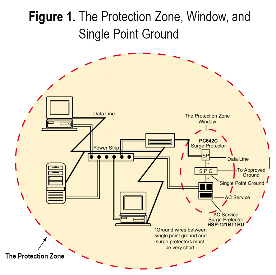
The Single Point Ground
The single point ground is a common ground point or node used in the protection zone to bond together all ground references inside the zone. Surge currents passing through a ground conductor generate a voltage across the conductor. This is primarily due to inductance of the wire. Inductance is highly dependent on conductor length; therefore, it is very important to keep suppressor ground wires to the single point ground very short.
The Protection Zone Window
The protection zone window is a hypothetical small opening in the zone through which all electrical conductors enter or leave. The single point ground is located at the protection zone window.
Figure 2 illustrates a typical installation of equipment within a small area; however, there are three problems associated with the installation depicted.
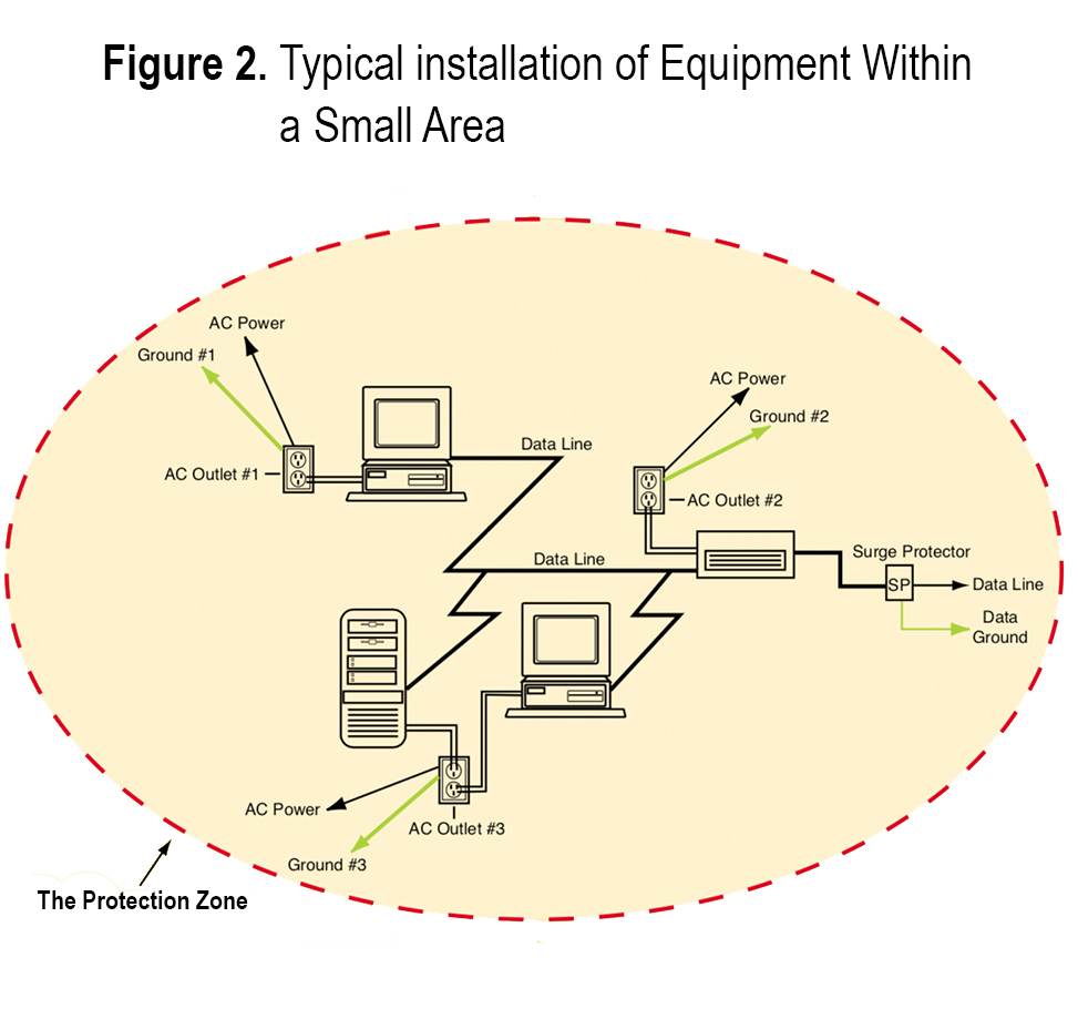
Problem #1
There are four ground references in Figure 2. AC outlet #1, AC outlet #2, AC outlet #3, and the data line all present separate ground references. The three AC outlet grounds are connected together at the power panel many feet away. The ground wire lengths offer enough inductance to effectively create separate grounds. In addition, the data line may run hundreds of feet to yet another ground reference in remote circuitry.
Problem #2
Notice in Figure 2 that there is substantial distance between various conductors leaving the imaginary circle of the protection zone. Even if ground conductors were bonded together, destructive voltages would exist during a surge due to wire inductance.
Problem #3
While the data line shows a surge suppressor, the lack of suppressors in the power receptacles leaves an opening in the protection zone. Even the best data line suppressor cannot prevent damage under these conditions.
The problems listed for the installation in Figure 2 are solved using the Protection Zone Concept. Figure 1 illustrates the proper installation:
- All devices are powered from the same AC outlet.
- The AC service incorporates a Model HSP-121BT1RU surge suppressor.
- The single point ground is established in the protection zone window.
- Data line suppressor(s), Model PC642C, are added at the single point ground.
- A ground bus bar is located at the ground area to facilitate multiple ground connections.
- Ground wires to the suppressors are very short.
- An optional (depending on code) ground conductor connects the ground bus to the main building power ground. This conductor may be quite long, but that does not create a problem now that the ground area has been established.
PROTECTING MULTI-BUILDING DATA AND CONTROL SYSTEMS
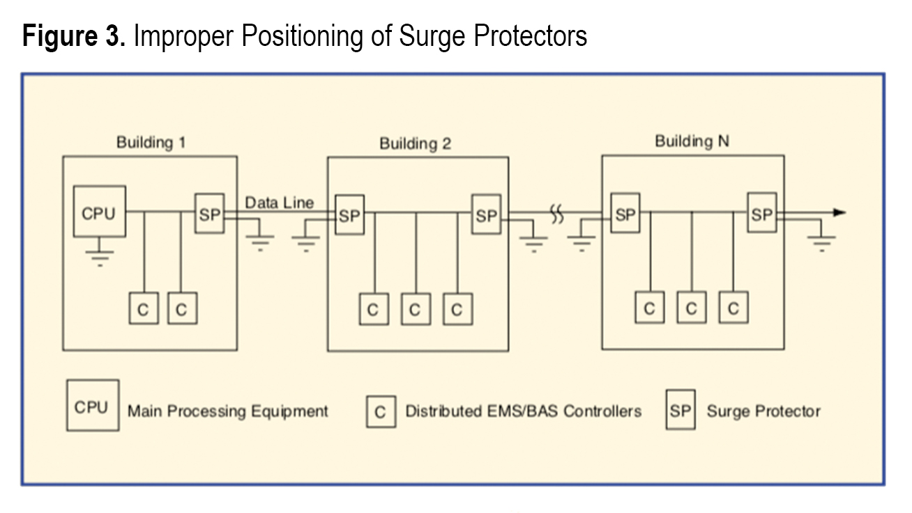
The Protection Zone Concept can also be applied to multi-building, multi-drop data and control systems. In Figure 3, the surge protectors located at the building entrance are improperly positioned to protect the CPU and the controllers. During lightning activity, ground potentials at opposite ends of a building can be thousands of volts, causing damage to electronic equipment.
Also, surge protectors for data lines that enter buildings have series resistance. The series resistance of the surge protectors is additive. The total series resistance often is too great and can cause communication or data line problems. The installation in Figure 3 shows five protectors in series over the length of the data line.
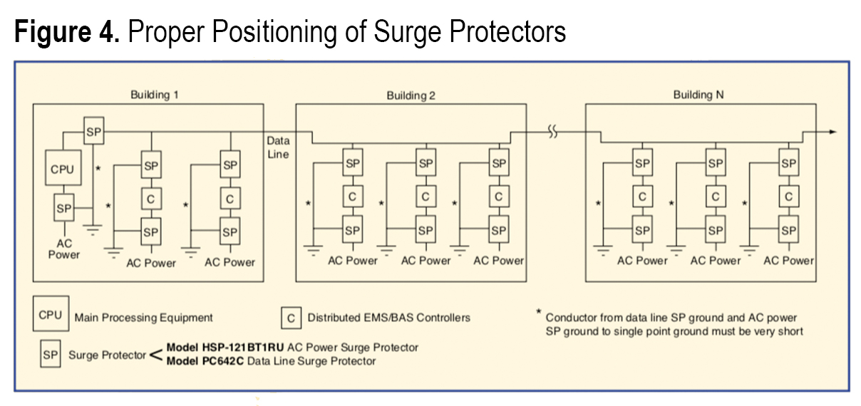
To properly configure surge protection on a multi-building, multi-drop system (see Figure 4), connect the surge protector on each controller drop so that the protector is not in series with the main data line. When connected in this manner, no more than two surge protectors are connected in series. Using the Protection Zone Concept, locate the data line surge protectors within the protection zone window along with an AC service outlet surge protector for each respective controller. Remember to keep the ground connections to the single point ground very short.
SUMMARY
Remember the following when applying surge protection:
1. Keep all grounds inside the protection zone at the same potential. If different ground potentials are present on electronic equipment, damage will occur regardless of the suppression used.
2. Protect all electrical and data circuits entering or leaving the protection zone at the protection zone ground window. Doing this keeps circuits at a safe voltage with respect to the ground window. This safe voltage is the clamp voltage (let-through voltage) of the respective suppressors.
The majority of surge protection installations are fairly simple and only involve bonding suppressor grounds to AC service grounds at the ground window. Existing sites may involve some rewiring to accomplish the best results. In order to keep the data line surge suppressor ground and AC service ground wires very short, wiring must sometimes be moved. When applying surge protectors, using the Protection Zone Concept will effectively protect EMS and BAS installations.


