Understanding Current Sinking, Current Sourcing, and Ground Loops
You’ve just purchased some current to pneumatic transducers and are ready to try them. Each transducer has been carefully installed according to the manufacturer’s recommendations and wired to its own 4-20 mA analog output. All of the transducers are being powered by a common 24 VDC power supply. Feeling confident with the installation, you decide it is time to test their operation. Individual commands are issued to each unit through the building automation system (BAS) but none of the I/P transducers appear to function properly. A command issued to one unit mysteriously causes all of the other units to react (or perhaps none of the units work at all). After mumbling a few choice words, the installation and all the wiring are verified to be correct. The system is trying to deliver a 4-20 mA signal to a device that is designed to accept a 4-20 mA signal. So what is the problem? Are all of the transducers defective? While this is possible, it is very unlikely. Instead, the problem could be directly related to the fact that all 4-20 mA analog outputs are not created equal.

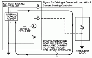
Different BAS controllers utilize different electronic techniques for generating a 4-20 mA current output. With one method, the analog output typically has its “I+” terminal connected to the “+” side of an internal current loop power supply whose “-” side is connected to “ground”. The output has its sensing and regulating electronics between the “I-” terminal and “ground” (See Figure A). The “I +” terminals are electronically identical. Because the “I -” terminals carry the different current values for each output loop, they must be isolated from each other. They cannot be connected together nor can they be connected to a common or “ground”. Connecting a 4-20 mA load from “I +” to “ground” puts the controller’s internal current loop power supply directly across the load (See Figure B). The controller’s regulating electronics are completely bypassed, which will usually cause the controller’s output fuse to blow, the load to go to full output and remain there or the load to be physically damaged. A computer using this type of 4-20 mA signal is commonly referred to as a “current sinking controller.”

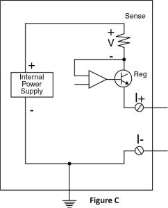
Another method used to generate a 4-20 mA signal puts the sensing and regulating electronics between the internal loop power supply and the analog output “I +” terminal. The “I -” terminal is connected to circuit “ground” (See Figure C). With this method, the “I+” terminals carry the different current values for each loop and, therefore, must be isolated from each other. Since all of the output “I-” terminals are electrically the same, they can be connected together. They may or may not be connected to “ground” depending on the manufacturer’s specifications. A controller using this method to generate a 4-20 mA signal is commonly called “current sourcing.”

Looking back now at the problem discussed previously, all of the I/P transducers are being powered from a common power supply. After a little research you determine that your controller is current sinking and upon further examination of the I/P transducer, its power input “-” terminal is found to be common with its signal input “-” terminal. Since all of the I/P power input “-” terminals are connected to one common power supply, this effectively ties all of the controller analog output “I-” terminals together. (A no-no for current sinking controllers.)
One way to solve this problem is to provide a separate isolated (not grounded) power supply for each transducer. This can be costly and, if panel space is at a premium, not very practical. It may also be necessary to isolate the case of a metal transducer from ground for proper operation. Another way to solve this problem is to configure the computer’s analog outputs for voltage output. Doing so will typically allow the controller to drive grounded loads as well as multiple loads powered from a single power supply. Transducers that are designed to accept a voltage or that are field selectable for current or voltage should, of course, be used (UCP-422-V, UCP-522, UCP-622). A third solution is to utilize two-wire transducers that are loop-powered and require no external power supply (UCP-422, UCP-242).
Another problem often encountered when interfacing a computer’s analog output to external equipment is the corruption of the control signal due to “ground loop” currents. Our instinct would lead us to believe that all “ground” points are at the same potential. In reality, however, there is no such thing as an absolute “ground.” Ground potentials at different locations are not equal because current flow in the ground conductors causes small voltage potentials to develop from one ground point to another. Connecting a wire between “grounds” creates a loop causing “ground loop” currents to flow through the wire. This causes voltage drops in the ground wire due to wire resistance (See Figure D). Also, since the impedance of the loop is rather low, a few volts potential difference can produce several amps of current, possibly damaging electrical components. Even worse, electrical storms could momentarily cause very large potential differences that would make an extremely large current flow possible. Under these circumstances, the current flow can be high enough to burn cables or destroy electrical interfaces.
One simple way to solve this problem is to isolate or float the “com” connection from ground at either end. However, the equipment often has its “com” terminal internally grounded, making it impractical to float. When this is the case, a signal isolator such as the Model DT13 should be used. The DT13 accepts a current or voltage input and produces a linearly-transferred current or voltage output. The input and output are electrically isolated making the DT13 useful for eliminating ground loops, reducing noise pickup, allowing conversion of the signal type (from current input to voltage output and vice versa) and scaling between the input and output. The DT13 could also be used to solve the problem discussed earlier by allowing current sinking controllers to control grounded loads.
The Model DT13 contains an internal power supply which provides regulated and isolated power to each half of the board. Input conditioning circuitry scales and filters the DC input and drives a precision isolator, which carries the signal across the isolation barrier. The output side of the isolator drives a circuit that reconverts the signal into a duplicate of the input, which can then be scaled as necessary for the application.


