Measuring Air Flow with Pitot and Averaging Tubes
Building Automation Systems are often required to measure the actual air flow in air handling systems. Although there are many ways to measure air flow, the two most commonly used with BAS systems are the hot wire anemometer and various devices which measure the velocity pressure of the air. Once the velocity pressure is known, the BAS is then able to calculate air flow. Each method has advantages as well as disadvantages.
The primary advantage of the hot wire anemometer is that it can provide an analog output that is proportional to flow, and no square root calculation is required to measure air flow. The disadvantages of the hot wire anemometer are that it measures only one point in the cross section of the duct, and it may require periodic recalibration.
Among the flow measuring devices that measure velocity pressure are pitot tubes and averaging tubes. The pitot tube may be used with a differential pressure transmitter to determine air flow at a relatively low cost. However, the BAS controller must be able to calculate the square root of the velocity pressure. Also, the pitot tube measures the velocity at only one point in the duct.

Figure 1 Measuring Air Flow
Figure 1 shows a typical pitot tube. In this diagram, Ps is the static pressure which is exerted in all directions (such as the pressure inside a balloon). This is sensed by the radial holes in the pitot tube. Pv is the velocity pressure caused by the momentum of the air moving in the duct. Pt is the total pressure and is the sum of the static pressure and velocity pressure (Pt=Ps+Pv).
The opening in the tip of the pitot tube measures total pressure. Since only velocity pressure is required to calculate air flow, the total pressure is piped to the high pressure port of a differential pressure transmitter, and the static pressure is piped to the low pressure port of the transmitter (see Figure 1). The differential pressure that is then measured is the velocity pressure (PV=PT-PS).
Once the velocity pressure is known, velocity may be calculated by the following formula:
-
-
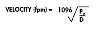 where Pv = velocity pressure in inches water column D = air density in lb/ft3
Air density is normally assumed to be 0.075 lb/ft3, based on 70°F dry air at 29.9″ Hg barometric pressure. If corrections must be made for barometric pressure or air temperature, the air density may be calculated by the following formula:
-
 where Pv = velocity pressure in inches water column D = air density in lb/ft3
-
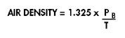 Where Pb = barometric pressure in inches Hg; T = absolute temperature (°F + 460)
 Where Pb = barometric pressure in inches Hg; T = absolute temperature (°F + 460)
If air density is assumed to be standard (0.075 lb/ft3), the output of the differential pressure transmitter may be used to calculate air velocity by the following formula:
-
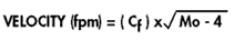 where Cf = Flow coefficient from Figure 3 Mo= pressure transmitter mA output
 - For accurate results, a differential pressure transmitter should be selected that corresponds as closely as possible to the velocity pressure to be measured. (See Figure below)
Figure 3 Flow Coefficients For Differential Transmitters
(For use with pitot tubes only)
Differential Pressure Maximum Transmitters Air Flow Range Velocity Coefficient Inches W.C Feet / Min Cf 0.1 1265 316 0.2 1790 448 0.3 2190 549 0.5 2830 708 1.0 4000 1000 2.0 5660 1420 3.0 6930 1733 5.0 8950 2240 ----
Once the air velocity is known, air flow in cfm is simply the duct inside area multiplied by air velocity.
AIR FLOW (cfm) = V x A
where V = average duct velocity (ft/min) A = duct cross sectional area *(ft2)
Notice that V is average duct velocity. When using a pitot tube, velocity can be measured at only one point in the duct. In a straight duct run, the velocity will be greatest in the center of the duct and lowest near the duct wall where the effects of friction slow air flow. The size and the shape of the duct determine how much the center velocity will deviate from the average velocity. To obtain an approximate average duct velocity when a pitot tube is installed in the center of a straight duct, reduce the center velocity by 10%. This will yield results that should be accurate to within ±5%.
To take some of the guess work out of determining average duct velocity, an averaging tube may be used. An averaging tube operates basically the same way as a pitot tube to determine average duct velocity pressure, except instead of measuring one point within the duct, the averaging tube measures multiple points to determine a true average velocity. As an added benefit, some averaging tubes are designed so that the differential pressure measured is two to three times the actual velocity pressure. This amplification is accomplished by the shape and design of the tube and results in greater resolution and the ability to measure lower air velocities.
When measuring air flow with either a pitot tube or an averaging tube, best results will be obtained when the flow measuring device is located at least 7 1/2 duct diameters downstream and 1 1/2 diameters upstream from any disturbance (elbows, obstructions, etc.). Also, for best results, straightening vanes may be used 1 1/2 to 5 diameters upstream of the flow measuring device.
In Summary:
Only the average duct velocity and duct cross section area must be known to determine air flow.
By piping the total pressure to the high pressure port and the static pressure to the low pressure port of a differential pressure transmitter, the velocity pressure will be measured.
When the duct center velocity is measured with a pitot tube, the average velocity will be approximately 90% of the measured velocity.
By using an averaging tube, the average duct velocity may be measured directly. The averaging tube may also amplify pressure for greater resolution and higher accuracy at low flow rates. Flow coefficients for use with averaging tubes will be provided by the manufacturer.
Always install air flow measurement devices at least 7 1/2 duct diameters downstream and 1 1/2 diameters upstream of anything in the duct that could cause turbulence.
Quick Tips…(for use with pitot tubes only)
By applying the two simple facts below, air velocity may be quickly estimated in the field.
1. 4000 fpm velocity = 1″ velocity pressure
2. Velocity pressure varies as the flow squared or:

Example:
If a velocity pressure is known, the velocity may be calculated by using 4000 fpm and 1″ differential as V1 and P1. Assume the velocity pressure is 0.25″. What is the air velocity?
![]()
If a velocity is known, velocity pressure may be calculated in a similar manner. Assume velocity is 1000 fpm, what is velocity pressure?
![]()
* This equation contains subscripts or superscripts which may not be supported by all web browsers. Contact your Kele Sales Representative if there are any questions about this formula.


