Air Flow Measurement
Measuring chilled water (or condenser water, or hot water) flow in your system can’t be that difficult, can it? After all, you just stick some kind of flow measurement device in your pipe and read its output, right? That depends on what type flow measuring device you install.
How many types of flow devices are there to choose from? There are types that create an obstruction in the pipe and measure the differential pressure across this obstruction. This includes the age-old orifice plate and venturi meter. Does your customer really want to pay for this pressure drop for the life of the building in order to measure flow? (At 10¢/kWh and continuous operation, a 1.65 psi pressure drop in a 1000 gpm flow will cost $1000 per year in electrical costs.) Another differential pressure type device is the averaging pitot tube. It typically operates on a lower pressure drop, which introduces another problem. It can be tricky measuring low differential pressure in liquid systems. Kele is glad to help by offering Model 360C differential pressure transmitters custom-calibrated to the differential pressure range of each application. Care must be taken in these installations to install the transmitter in the correct location, eliminate air pockets, and keep the instrument piping free of dirt, rust, and corrosion which may block the transmitter sensing ports.
How do you determine flow based on the output of a differential pressure transmitter? The manufacturer of the primary sensing element must furnish information to allow you to calculate flow, but with ALL differential pressure devices a square root calculation is required. This is due to the fact that the flow rate varies as the square root of the differential pressure. Once again, Kele comes to the rescue with the UMM-1-SQ math module with square root function. These types of devices are also accurate only at relatively constant flows. This has nothing to do with the quality of the flow sensor or the differential pressure transmitter, but is just everyday physics due to the square root function. See Figure 1 for an example of this principle.
There are a variety of meters that utilize different physical principles to accomplish flow measurement. These include positive displacement meters, in-line turbine meters, vortex shedding meters, target meters, electro-magnetic
meters, ultrasonic meters, and Doppler meters. All of these have their place in flow measurement and work well in specific applications. However, their price is generally high for HVAC applications.
Two more types of meters include the insertion turbine type and the impeller, or paddlewheel type. They both create very little pressure drop. They also measure flow velocity directly, so that no differential pressure transmitter and square root extractor is required. Their average installed cost is lower than the meters mentioned above.
The insertion turbine has a shaft parallel to the flow, requiring blades to have a helical twist because of their orientation to the flow direction. The shaft and bearings are in the flow stream and exposed to impurities in the liquid. The paddlewheel meter, such as the Data Industrial 200 Series, has a shaft at right angles to flow and the shaft and bearings are located out of the flow stream. The free spinning lightweight paddlewheel is almost neutrally buoyant and is non-magnetic. This allows trouble-free, accurate operation at low flow rates. The encapsulated electronics of the 200 Series flow sensors provide an output to the flow transmitter which is proportional to flow, so that no square root extractor is required.
The output of the 200 Series flow sensor may be utilized with a variety of flow transmitters and BTU Monitors to determine instantaneous flow rates, totalized flow, or BTU measurement. See Page 8 for more information on these devices.
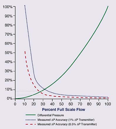 Figure 1. Accuracy of Differential Pressure Type Flow Measurement (Assuming differential pressure transmitter is calibrated for 100% flow rate)
How to use this chart:
- Select on the horizontal scale the PERCENT FULL SCALE FLOW at which you wish to check the Differential Pressure and Measured Accuracy.
- Trace vertically until you intersect the appropriate curve.
- From the vertical scale on the left read the appropriate values.
Example:
A Differential Pressure Transmitter is used with a differential pressure type flow element and calibrated for 0-100”W.C. at 1000 gpm flow.
The transmitter is 0.5% accurate at full scale. What is the differential pressure and measured accuracy at 300 gpm flow?
300 gpm is 30% of full scale flow, so at the 30% point on the PERCENT FULL SCALE FLOW scale, trace vertically until you intersect the Differential Pressure line and read on the vertical scale a value of 9%. The differential pressure under these conditions is 9% of 100”W.C., or 9”W.C. To determine Measured ÆP Accuracy, trace vertically from the 30% point until you intersect the Measured ΔP Accuracy line for 0.5% accuracy transmitters and read on the vertical scale a measured accuracy of ± 5.6%. This inaccuracy is due to the reduced differential pressure and does not include inaccuracies of the flow sensing element.